A anti-spy or bug detector circuit is a device that detects hidden wireless electronic devices such as wireless microphones, spy cameras, Wi-Fi devices, GPS trackers or any gadget that emits some kind of radio frequency (RF).
The proposed design can be specifically used as:
- Wi-Fi Signal Detector Circuit
- FM Transmitter Signal Detector Circuit
- Wi-Fi Spy Camera Detector Circuit
- Wireless Mic Detector Circuit
Overview
Also called anti spy RF sniffer, these are usually used to scan and detect hidden electronic surveillance, that may be installed to secretly monitor a "target" or an opponent and secretly learn about their plans.
Bug devices are mostly used by detective agents, police, and secret agents for tracking the behavior of a suspected criminal, or a personal client.
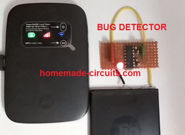
The bug detector circuit presented here is exclusively developed by me, and can be used for detecting, pinpointing any hidden wireless device or unwanted surveillance planted in a room.
The hidden spy devices could be inside beds, cupboards, tables/chairs, flower pots, or in fact anywhere a normal individual would least suspect.
Identifying such hidden unwanted surveillance system can be impossible without using costly and sophisticated equipment. However, the circuit idea presented here is not only cheap to build, it also accomplishes the job with utmost perfection.
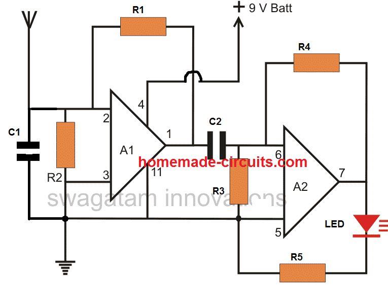
The complete circuit diagram can be seen below:
Video Test Result
NOTE: the sensitivity of the circuit can be adjusted to much higher levels either by increasing the 2M2 resistor value, or by adding two more op amp stages in series with the above design, since we already have two extra op amps in spare inside the IC.
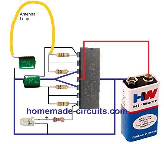
Pictorial Presentation
Circuit Description
The circuit is basically built using the quad op amp IC LM324. Although the IC has 4 op amps in-built, only two op amps are actually implemented for the bug detector application.
The A1 and A2 stage are identical and both are configured as high gain inverting amplifier circuits.
Since the two amplifiers are joined in series the total gain is highly enhanced making the circuit highly sensitive to RF interference.
Basically the amplifiers work through the following steps:
- The antenna picks up the electrical the disturbances, sends it to the op amp amplifier A1, which amplifies it 10 to 100 times depending on the value of the feedback resistor R1.
- The output from A1 is sent to the next op amp A2 via C2, which blocks the DC ad allows only the picked AC frequency.
- A2 further amplifies the frequency 10 to 100 times depending on the resistor R4. C1 ensures stability to the op amp and avoids stray pick ups.
- R2, R3 ensures the op amp inputs act like differential inputs for detecting minute changes in the received electrical signals.
The circuit is so sensitive that it is easily able to detect all types of electrical noises even thunder lightning interference.
I was surprised when I saw this bug detector circuit easily picking up signals from my wireless Wi-Fi device from a distance of 2 feet. Actually, while the unit was placed on the bed, I found the LED blinking abnormally as if the circuit was unstable and malfunctioning. I was quite disappointed.
Then I picked it up and put it some distance away from the bed, and the LED just shut off. I tried placing it again on the bed and the LED started blinking again. I still couldn't figure out the reason, and thought may be the bed was acting like a large antenna and causing the disturbance.
However, finally I realized that this was happening because my internet WiFi unit was also placed on the same bed at some distance away.
I removed the WiFi device from the bed and the bug detector LED was simply shut off again.
Next, I did a number of repeat tests and was convinced that the unit was actually detecting RF, and the LED blinking wasn't due to an unstable or malfunctioning condition.
Once confirmed I built the final bug detector circuit and presented it here for your reading pleasure!
Parts List
- R1, R4 = 2.2 Meg
- R2, R3 = 100 K,
- R5 = 1 K
- C1, C2 = 0.1 uF PPC
- A1, A2 = 1/2 LM324 op amp
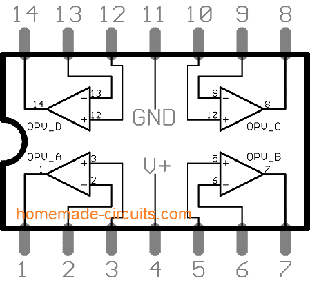
LM324 pinout details can be found below:
Fully Transistorized RF Sniffer, Bug Detector
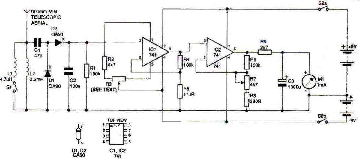
This small, fully transistorized circuit may be used as a permanently attached transmitter RF monitor, or a close-range transmitter RF detector or both. No tuning coils are necessary! A 9 V transistor radio battery is used to power the gadget.
For transmitter hunting, the loop antenna may only need to be as small as the diameter of a hand (approximately 250 mm) or even less.
You may create a fairly sturdy antenna by engraving a circle or square on a suitable piece of PC board. The other parts might also be mounted on the board.
You might use a folded dipole or a loop that is a wavelength long at one frequency (VHF, otherwise it would be enormous practically).
Transistor Q1 is biased by means of R1 and D1, and changing the bias by means of RV1 allows for sensitivity adjustment.
The antenna loop's signal is corrected by the diode D1-C1. Q1 and Q2 dc-amplify the rectifier's output, forcing a meter deflection in Q2's collector circuit.
At the collector of Q2, any amplitude modulation on the signal received will be displayed.
This is capacitively connected to the base of Q3, amplified, and supplied to dynamic headphones having low or medium impedance and not a high impedance.
This final step may be skipped if simply meter indication is needed.
RF Sniffer Circuit
The circuit diagram for the RF sniffer can be witnessed in the following figure. RF signals heading at ANT1 are connected through C5 towards the detector circuit stage.
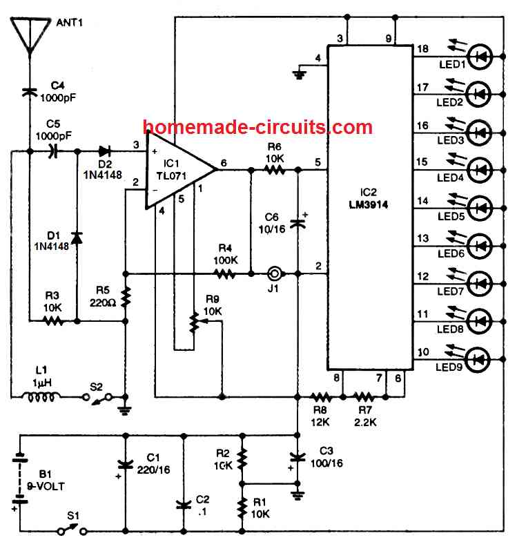
A high impedance ground network intended for wide band detection is supplied by R3.
Having inductor L1 hooked up to the circuit by means of S2, the circuit gets adjusted for the FM band. Diodes D1 and D2 perform the job of detection and demodulation.
The detected RF signal is transferred to the non-inverting input of op amp IC1 .
The IC1 op amp is constructed like a non-inverting amplifier through a preset gain of approximately 450.
The circuit works by using junction field effect transistors (JFETs) at the input sections; which boosts sensitivity because of their high impedance.
Potentiometer R9 works like a squelch control which tunes the IC1 offset settings. The amplified detector output which shows up on pin 6 of IC1 is transferred to J1.
An appropriate high impedance phone could be attached to J1 whenever you would like to hear the detected signal.
Furthermore, R6 and C6 do the job of cleaning the signal. The cleaned up signal is subsequently given to the input of IC2, which is an LM3914 dot /bar display chip.
The LM3914 or LM3915 device includes a network of resistor and a range of comparators.
With respect to the input voltage fed to pin 5, several LEDs will probably light up to show the relative voltage levels.
In this RF sniffer circuit, a 9 LED bar display is set up by attaching pin 3 of the IC2 with the positive supply voltage.
When the detected signal is the weakest, this might illuminate only the LED#9.
As the detected signal voltage becomes stronger, each of the LEDs in the bar graph turns on one by one until, with the most powerful RF signal level, you might find all the nine LEDs being illuminated.
Resistors R7 and R8 are used to fix the reference voltage for a full-scale bar graph LED display.
Observe that we have not used any current-limiting resistors for the LEDs; since the resistors R7 and R8 itself fulfill the function of limiting the LED current.
Parts List
For further inquiries or information please use the comment box below.
RF Sniffer Using IC 741 and Meter Reading
The RF 'Sniffer' device discussed in the following article is capable of detecting RF radiation across a broad range, from approximately 100 kHz to VHF to 450 or 500 MHz, and it will assist in locating and identifying low-power espionage transmitters.
The majority of designers will already have the components in their spares collection (and if not, these are not costly), and the device can be put together in a single evening.
Therefore why not investigate your workplace or house and alleviate those persistent fears?
Circuit Description
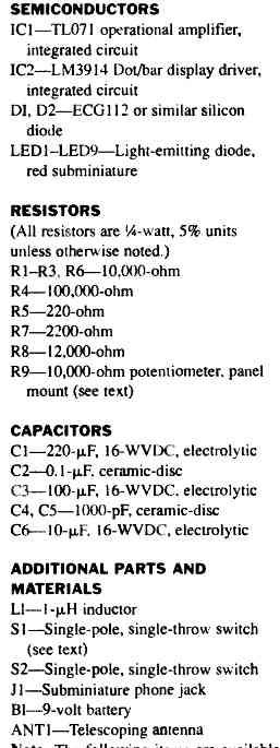
The following figure shows the circuit diagram of the device.
A voltage-doubling circuit made of diodes, D1 and D2, and C1 rectifies RE signals captured by a short telescopic antenna. The operational amplifier Cl's non-inverting input receives the resultant dc.
The low value capacitor, C1, and the RF choke, L2, work together as a straightforward high-pass filter to stop the device from reacting to low-frequency ac fields.
In order to bypass low, medium, and some of the higher radio frequencies and further stifle the unit's responsiveness, a lower inductance RF choke, L1, can be switched into the circuit. R1 serves as a load for the voltage doubler, while C2 shunts any remaining RF to ground.
R4 and R5, which control the amount of feedback to the amplifier's inverting input, set the gain of the circuit.
The meter's pointer may be adjusted to zero in the absence of a signal thanks to the resistor arrangement R2 and R3.
The non-inverting input of IC2 is linked to the output of the first operational amplifier. By adjusting the potentiometer R7, which controls the degree of feedback across the second amplifier, the device's sensitivity may be changed.
R9 calibrates the metre to read about 3V FSD and guards against movement damage should the second IC experience saturation. Any erratic variations in the output are smoothed down by C3. S2A and S2B switch the dual 9V-0-9V battery supply into the circuit.
Components
To enhance the frequency responsiveness and sensitivity of the device, point-contact germanium diodes for DI and D2 should be employed (they operate at lesser forward voltages compared to silicon diodes).
A 0.25-watt 1 megohm resistor's body may be made into a suitable small RF choke by winding 30 turns of 34 or 36 SWG enameled copper wire around it. Alternatively, suitable micro RF chokes cn be also procured from an online store.
As an indication, a low-cost signal strength or "VU" meter will work.
These meters typically have a sensitivity of 200 uA, thus shunting or raising the value of R9 will be necessary to provide the necessary 3–4 V full scale deflection. A 1 or 2 mA meter would do for this application with the value of R9 as specified as meter sensitivity is not crucial.
How to Set Up
If D1 and D2 are made of clear glass, they need to be protected from light before setting up the experiment.
When the unit is set to high sensitivity, the photovoltaic impact of the diode junctions is sufficient to swing the metre pointer sharply over.
Inspect the circuit board for poor soldered connections and bridged copper tracks as normal. Also, make sure the diodes, op-amps and C3 are oriented correctly.
Attach the 4K7 preset temporarily in the R3 position (that is, to R2 and pin 5 of IC1, with the slider connected to pin 4 of the IC) and adjust it around mid-way of it rotation.
Turn on the power supply after disconnecting the meter. Each battery should only use about 2.5mA of current.
Replace the 1 mA meter movement with a test ammeter and set it to read 5 or 10 mA FSD. Bring the cursor to zero by adjusting the 4K7 setting.
The default slider is probably going to be significantly off-center. Keep track of whether the potentiometer's higher resistance leg connects to pin 5 of the ic or R2.
The 1 K potentiometer, which will serve as the real set-zero control, should be connected in the R3 position. The preset should be wired in series with the leg that will serve as its high resistance.
Adjust the preset to return the metre pointer to zero after setting the 1 K potentiometer to mid-travel. Attach the 1 mA movement to be used in the Sniffer after disconnecting the test meter.
Making any required tweaks to the preset, confirm that its pointer is capable of being brought to zero with the sensitivity control adjusted to maximum and the I K slider adjusted to zero control at center travel.
Measure the preset resistor's resistance and replace it with a fixed resistor, RX, of the nearest standard value.
When the 4K7 resistor, R2, was connected to pin 1 of the ic, offset nulling was consistently obtained when a variety of 741 op-amps were used in the IC1 position.
Connect the 4K7 pre-set straight to pin 1 of the ic in the unlikely event that the meter refuses to zero (i.e., short out R2).
If you find a null generated with this configuration, pin 5 and R2's connection to the potentiometer must be established.
It takes longer to discuss this setting-up process than it does to actually accomplish it.
Due to the high gain of two cascaded amplifiers, the standard 10K nulling potentiometer that is connected between pins 1 and 5 is impossible to tune.
The nulling or set-zero control has considerably gentler action since just a tiny area of the potentiometer is movable.
The configuration explained above is effective once the setting-up procedure has been completed.
For IC1, a high-quality instrumentation type op-amp having an extremely small input offset current could have been used, however these types of opamps are quite costly (and less likely to be accessible from spares containers).
Switch out L1 and check the RF sniffer by moving it very near to an electromagnetic source.
How to use
It is advisable to test out the device at home before going on a " seek and eliminate" expedition since using the instrument and interpreting the comparison scale readings require a certain amount of expertise and experience.
This is not the place to go into detail on eavesdropping bug circuitry.
It is sufficient to note that basic models of these micro-transmitters operate inside or near the VHF FM broadcast band and emit roughly the same amount of RF energy as a single bipolar transistor, such as a BC547 wired as an LC tuned oscillator and coupled to a short aerial.
This type of circumstance will forcefully knock the indicator pointer over at distances of three to four metres. The sensitivity of this Sniffer circuit is reduced at higher frequencies (450 mHz and above), where more unusual bugs typically function.
However, when the aerial of the device is close enough to the transmitter, it will clearly indicate the electromagnetic field.
The device will detect frequencies down to around 100 kHz when the low inductance RF choke L1 is disabled, and the meter pointer will be repelled by signals emitted by broadcast transmitters that operate on the long and medium wave regions.
Because the house wiring and metal objects (such as bed springs and mirror silvering) amplify these broadcast RF fields, the sensitivity control on the Sniffer must be reduced in order to detect any low frequency transmissions within the structure.
It may be helpful to tweak the set zero potentiometer in order to eliminate constant background radiation.
In order to make the Sniffer immune to bothersome lower frequencies, it should typically be operated with L1 switched ON into circuit.
Micro-transmitters used for eavesdropping typically broadcast at VHF and higher. Despite this, it is most effective to unplug personal computers, VDUs, and TV receivers from the electrical grid while conducting a search.
Certain bug transmitters are intended to be triggered by a phone call to the room or office for a predetermined amount of time.
Before beginning the search, make a call from a nearby room or arrange for the phone to start ringing.
Likewise, bugs may be set up to only broadcast when a phone call comes in, and a link should be established with the "speaking clock" while the survey is being conducted.
Drag the Sniffer aerial over any light fixtures, suspended ceilings, desks, other furniture, artwork, wall clocks, and similar objects.
Consider where you may hide a bug if you were keeping an eye on the space. Brilliant individuals probably have similar thinking.
Let's hope you weren't being overly cautious after all!
How the Circuit Works
C1, D1, and D2 work together to convert the RF voltage that develops across either or both of the input inductors to dc and doubles it.
As soon as the RF voltage changes are negative, a charge is created across C1 that is contributed to the positive voltage swinging.
Operational amplifiers IC1 and 1C2 are both linked in a closed-loop, non-inverting mode with feedback being applied to the inputs that are inverting.
A potential divider across each device's output is the source of the negative feedback.
With this configuration, R4+ R5 / R5 determines the gain of IC1, which is roughly 214.
The gain of this stage may be adjusted between 21 and 304 by introducing potentiometer R7 into the bottom leg of IC2's feedback network. Consequently, the unit's total gain can be anywhere between 4500 and 65000 times.
Op-amps are not infallible, thus there will unavoidably be a little imbalances in the differential input circuitry when there is no signal.
This circuit's maximum capacity for amplifying this modest offset current will cause the output stage to become saturated, hence it is necessary to make arrangements for cancelling it out.
This function is carried out by the ICI's nulling circuitry's potentiometer R3, which is hooked up to it.
Considering the gain offered, it is crucial to alter the offset nulling or set-zero control. In order to lower the control voltage on the potentiometer's track, resistors are arranged in series with it.
By doing so, its activity is constrained to the crucial nulling zone, making it simple to bring the metre pointer to zero.
For IC2, offset nulling is not necessary. By applying the required compensation voltage to IC2's input pin, the nulling features focused on ICI balance the entire circuit.
The metre is calibrated to read about 3V FSD using series resistor R9.
Since the 741's output impedance is so low in this circuit, it can supply enough current to harm a delicate meter movement.
If a meter with an FSD below 1 mA is used, increase R9 or attach a shunt.
In order to avoid abrupt output changes from creating erratic pointer swings, a high-value capacitor C3 is wired across the meter because inexpensive meters are unlikely to have significant electromagnetic dampening.


Comments
Hello sir,
Thanks for exposing such a usefull circuits.
I’d like to ask you if these circuits are able to detect RFIDs embedded In the body and wich one is the best.
I don’t haver any experience, I just have curiosity on trying to make one of these circuits.
With sincerelly thanks,
José Afonso
Hi Jose,
I don’t think the above circuits will be able to detect infrared RF, it will be able to detect only electromagnetic RF high frequencies, such as from mobile phones or WiFi devices.
I guess RFIDs emit infrared radiation and not EM radiation.
Thanks Mr Swagatanm for the kwick answer, that I real appreciated.
You don’t know where I can get one?
Thanks you
José Afonso
You are welcome Jose,
Sorry i have no idea from where it can be procured from, but i think you can try using a PIR module for detecting IR radiation from the RFID. Just make sure that the PIR does is not able to detect your body IR from your hand or any other part of the body.
how about detecting GPS tracker?
Can you please explain what C1 is doing here?
You wrote “The A1 and A2 stage are identical” which confused me a bit. The 2nd stage uses C2 I assume to isolate the AC signal, while in the 1st stage the capacitor C1 is in a different location and it’s not clear to me what it is doing. I would expect C1 to be on the other end of the antenna to isolate AC. Thanks!
P.S. If you do not use C1 as a high pass filter to block DC, how did you pick its value of 0.1uF?
C1 is for blunting the sensitivity of the antenna and to make sure only the strongest signals are detected. Removing C1 will cause the LED to switch ON permanently detecting and indicating all the possible noises available around the antenna. A1 and A2 are identical since they both have identical configuration and both are used as RF amplifiers.
Got it! Thanks for your prompt reply. So you picked 0.1uF based on the frequencies you are trying to select for/pass, in the 400-2000MHz range, yes?
I had been analyzing this for a week and should’ve asked sooner. 🙂
That’s right, although I picked it randomly, it ensures only a certain range of frequencies are allowed to pass, rest are grounded.
THE PROJECTS ARE VERY GOOD, SIMPLE AND FUNCTIONAL, AND CAN BE DONE AT A LOW COST, EXCELLENT FOR WORKING WITH STUDENTS FROM BASIC PRIMARY AND BASIC SECONDARY, THANK YOU.
Thank you for your kind feedback, much appreciated!
Hello, I made the same circuit with a breadboard. The LED does not show any sensitivity to RF signals, the light does not turn on. I checked my circuit. I couldn’t see any difference. Is there anything in the circuit that is not suitable for doing with a breadboard? I made the connections with jumper cables used in the breadboard. Could these cables act as an extra antenna and cause the circuit not to work, since they make too much length in some places? What could be the problem?
Hello, there might be some mistake in your circuit connections or the parts. Breadboard is definitely not suitable for this project since a single loose connection can result in the circuit failing to work. You will have to solder the parts over a strip board to make it work.
The circuit has been tested with cellphone also, you can checkout the video in the following article:
https://www.homemade-circuits.com/how-to-make-cell-phone-rf-signal/
Hello,
Can you answer a question for me please. As a retiree and old school HAM (N7VVC back in the day) I would like to assemble a few things, camera detector, IR detect, sniffer and the like. Not so much for me rather family to use.
My question is, can you suggest a seller of quality kits (complete components and parts)? Just a lot easier to for me at this time to have what I need and put it together.
Thanks. NR
San Diego CA.
Hello, I am sorry, I do not have any information regarding any seller dealing with these items.
Hello sir how are you hope you fine khalid here .sir thankyou very for your help sir i got success in making of 5kva inverter thanks sir. i complete the 5kva inverter and everything is fine frequency i set to 50khz and work fine but i not checked the output because the ferrite core transformer giving some humming sound not very loud very slow but i afraid may be burn so swith off i already put masking tape on outside leg of ecore when i hear sound from tansformer i put masking in middle leg also on ferrite ecore but still have sound so there is no problem with small sound or problem .we can use or it may burn or having any solution for sound please need help sir waiting for reply. And complete report i will give after checking the output and load test so please reply i am waiting for reply thaks.
Thank you Khalid, but you have posted the question under the wrong article.
Please post this question under the following relevant article:
https://www.homemade-circuits.com/5kva-ferrite-core-inverter-circuit/
I will try to figure it out for you.
I have a camera happy landlord who I believe has audio in my home without any power whatsoever through out the Nabor hood and only his generator running at the main house about 75 yards away I still get Rc single stronger than calling out on my iPhone and it seems to run in a line across the wall and I’m not getting anything from my TVs pa speakers or anything magnetic just in spots on the wall and a line running across it too
Should I have Rc without any power to my house at all and like I said it’s more powerful then my cell phone. Help please am I being bugged or just nuts??
Switch OFF your home power completely and switch OFF all the electronic gadgets in your home and check again for the RF. If it still exists strongly inside your house then probably you are bugged
what kind of capacitor you use? the cirtuct can woks with 5v?
any good quality capacitor will work!
Hi,
My name is Mike Grupe and I am currently studying electrical/electronics engineering at the University of Southern Queensland, Australia. I don’t have much practical electronics experience but after checking out this website – wow!!! Awesome!!! This will enhance my electronics knowledge – a big thank you, my journey in learning electronics just got a little bit easier.
Keep up the good work.
Thanks again,
Mike
Hi, thanks very much, appreciate your enthusiastic thoughts, and wish you all the best!
Sir;
I am interested in eaves dropping detectors. I am a retired Texas Peace Officer, and I head up the security at my church.
First: What antenna configuration or specs are required to recieve a broad range of bands, from cell phones, wifi, GPS on cars, and most things that eaves drop in an office enviroment? In other words, can I build a unit that will use one antenna, and pick up anything in this spectrum?
Second: I would like to be able to “tune” or adjust it, to pick up such signals from about 30 feet away, and set it for a lower sensitivity as I enter the particular room, or closet the bug is broadcasting from. Is this feasible? Maybe a row of LEDs that light up in a range depending on proximity to the bug, or strength of signal.
Respectfully,
Retired L.E.O.
Hello Mr. Robert, I have one related circuit already posted in this website which is designed for listening to GHz bands, I got this from one of the old electronic magazines. Here’s the link of the article, I hope this does the job for you:
https://www.homemade-circuits.com/listen-to-uhf-and-shf-ghz-bands-with-this-simple-circuit/
I need that one too sensitive rf detector for personal use.. can you please tell how much cost charge for making this type of rf detector .if it is possible I want to buy it if you make it for me. Contact personally on my mail.
If you make it too sensitive, the LED will keep blinking all the time, because RF is present in our home through many different sources, from AC mains lines, from refrigerators, neighboring mobile phone calls, computer, tube lights, fan dimmer etc. Sorry I do not sell this item I can only help the user to build it personally.
Can’t we use any other IC ?
No, LM324 is the recommended iC.
I don’t have a 324 but I have LM3900N. The pinout is different so I’ll need to make sure I have everything in the proper places. Do you think LM3900N will it work as substitute?
I would recommend LM324 only, which will give guaranteed results, i am sire how other op amps might work.
Can you explain me the working of each component in the circuit as I am doing my mini project on this circuit?
I have updated the explanation in the article….
Can you explain the circuit diagram it’s quite confusing
Can I use normal capacitors instead of ppc capacitors
You can use any good quality capacitor
Can you explain circuit diagram connections ?
You can get more explanation here
https://www.homemade-circuits.com/how-to-make-cell-phone-rf-signal/
first, I want to thank for this project
second, I couldn’t find a 2.2 M ohm resistor, so I used 3.3 M instead, so the LED won’t blink until it is in direct contact with the signal transmitter, I think I should search for 2.2 M resistor and replace them in order to increase the sensitivity, or what you do say?
higher resistance value at the feedback will increase the sensitivity of the circuit and may make it unstable…you can use two 1M in series if you are not getting 2M2.
Can I use ceramic capacitors or do I absolutely need PP capacitors ??
PP will work better according to me
I want to ask ;is there high and low voltage protective circuits used 324
220vac
It is there, please use the search box above to find it.
Actually I’m having trouble figuring out how to wire any of it together. Could you possibly post a photo of the under side of the pcb to show how you connected all the components together, please? It would be very much appreciated !
Hi, the soldering side is quite messy so it won’t help much. Instead I have updated it in the pictorial form with all the connection details. you can check it now…I hope it helps!
The pictorial is a tremendous help, thank you so much for taking the time to explain the connections!
Glad it helped, wish you all the best!
Any ideas on how/why it works at all?
From purely theoretical point, it shouldn’t work, because…
1) C1 shorts antenna input to ground in terms of AC (RF input). In case of “ideal” capacitor, 0.1uF would be pretty much negligible impedance for anything that looks like RF.
2) Gain-bandwidth product of LM324 is nowhere close to wi-fi or cellular, it isn’t RF device on its own.
3) There is no obvious explicit RF detector circuit either. So where does RF turns into something LM324 can process, how and why?
As reasonable guess, “real” parts would have plenty of parasitic parameters, say, most 0.1 uF caps would have some “resonance frequency” far lower than cellular or wifi. Past that point they rather behave like inductance instead, due to parasitic inductance of leads/plates overtaking capacitance action. However it isn’t obvious and if one means it have to be inductor, using “explicit” inductance with specified parameters is probably better idea? Then, I can imagine strong RF field can manifest itself by detecting on either ESD protection of inputs, or on input BJT junctions or so, however it nowhere close to being obvious and it would be my best guess I can do, could be incorrect.
p.s. also drawing + and – on opamp inputs in schematics could be good idea. Say I do have LM358 or 2904, at first glance it seems this circuit needs just 2 opamps, these should do as well, unless circuit relies on some extremely unusal parasitic properties of LM324 I’ve failed to foresee. In case of your circuit I have to scroll between IC pinout and diagram to “translate” it into to LM358-based version. Should there be + and – I would rather just redraw circuit by attaching functional pins the way circuit means it – at the end of day I’ve got curious why the hell THIS works at all. So if it actually does, I would definitely bug few “advanced” RF engineers to properly decode how and why it detects anything at all – I bet it can puzzle even seasoned RF engineers 🙂
Thanks for compelling to investigate this circuit more deeply 🙂
Actually there’s nothing complex about the functioning of the circuit. The op amps are honestly doing what they have been designed to do.
Referring to A1, the non inverting (+) pin3 is tied to ground, and pin2 is also at ground potential via the 100K resistor but is not as grounded as pin3. This makes it highly sensitive to any electrical disturbance even at mV range.
It has nothing to do with the frequency of the RF, it is merely detecting the electrical potential that hitting pin2.
Since the RFs may be fluctuating from across positive and negative cycles, the negative cycle which are more negative than pin3 potential are quickly caught by pin2. causing the output pin1 to go high. This high feedback quickly reaches pin2 back shutting it down, and the cycle is continued causing the LED to flash.
The 0.1uF is actually introduced to blunt of the sensitivity and prevent the circuit from detecting the unwanted disturbances emanating from other possible RF.
I am sorry redrawing the diagram may not be possible because this schematic has been indexed by Google, replacing it may not be good for the article, for the future articles I’ll surely consider adding the +/- to all op amp circuit.
Hi- Thanks for sharing this project! I’m new to diy electronics, would you mind sharing how you wired the antenna to the pcb and also how you wired the battery? Thank you!