In this article I have explained how to build a simple bicycle speedometer circuit which can be used to measure the speed of the bicycle.
Video Demonstration
What is a Bicycle Speedometer, How it Works
Bicycle speedometer is a device which checks the rotation per minute of the bicycle wheel and displays the results over a meter to indicate how fast the bicycle is travelling.
Basically, a bicycle speedometer works in the following manner:
- A sensor is installed on the one of the wheels of the bicycle.
- The sensor is usually a magnet based sensor, such as a magnetic hall effect sensor or a magnetic reed switch sensor.
- The hall effect sensor or a reed relay is installed on wheel frame of the bicycle, and the magnet is fixed on the wheel itself.
- The sensor and magnet are fixed in such a way that when the wheel rotates the magnet comes face to face with the sensor on each rotation.
- In this way on each rotation of the wheel, the magnet creates an instantaneous magnetic field on the sensor which cuts through the sensor generating a corresponding electrical pulse at the output of the sensor.
- This electrical pulse is fed to a processor which analyzes the sensor output pulses corresponding to each rotation of the wheel, and displays the result over a meter.
- The meter thus indicates the speed of the bicycle.
Which Concept is used for our Circuit
In this article we are going to explore 3 fundamental ways of making a bicycle speedometer circuit:
- By Integrating a Meter with Dynamo
- By using LM3915 Circuit and LEDs
- By using Hall effect sensor and magnet
1) Simply using a Voltmeter
The easiest way to check how fast your bicycle is moving is to connect a small digital or an analogue voltmeter with your existing bicycle dynamo as shown in the following image:
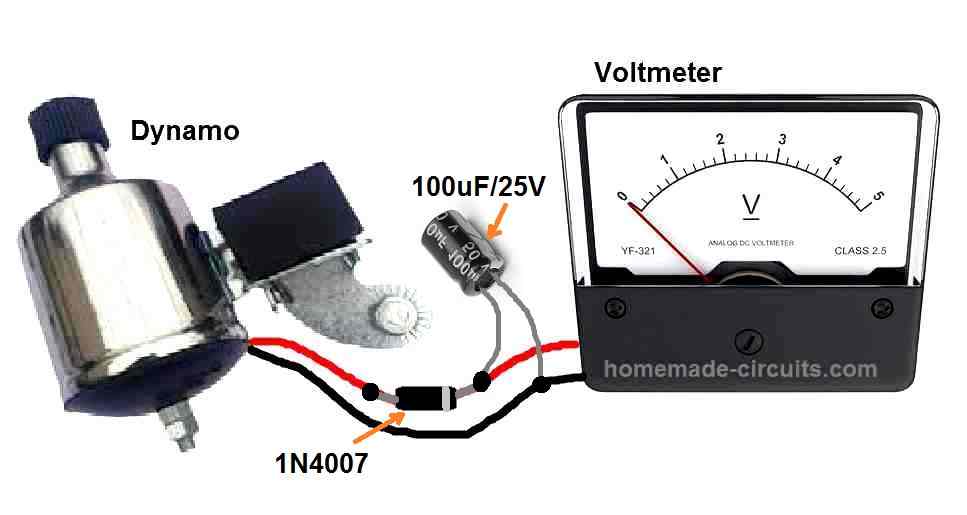
As shown in the diagram above we have a 0-5V voltmeter connected to the dynamo wires through a 1N4007 rectifier diode and a 100uF filter capacitor. This filter capacitor could be increased to 1000uF to reduce the vibration on the meter needle at slow bicycle speeds. The positive lead of the capacitor is connected with the cathode or the banded side of the 1N4007, and the negative lead of the capacitor is connected directly with the other wire of the dynamo.
Here, the indicated meter has a maximum range of 5V, but you can use a meter with higher range upto 12V or 24V, depending on your dynamo's maximum voltage generating capacity, with regards to the maximum speed of your bicycle.
The working of the circuit is simple. The voltage output of your bicycle dynamo is proportional to the speed of your bicycle wheel.
Meaning as the dynamo shaft is rotated faster and faster in response to your bicycle's increasing speed, the same is detected by the voltmeter, and the voltmeter shows a proportionately increasing volt reading on the meter.
This volt reading being directly proportional to your bicycle speed, indicates the speed of the bicycle.
2) Using LM3915 IC
In our second concept I have explained how to make a bicycle speedometer using IC LM3915.
The analogue voltmeter shown in the above concept can be vulnerable to vibrations and shocks which are quite common while riding a bicycle over a bumpy track.
This could cause the meter coil to get dislodged and get damaged.
This means, if the meter could be replaced by some kind of digital or solid-state system could make the system extremely reliable and fail-proof.
Using an LM3915 based 10 LED bar graph display for indicating the speed appears to be a good solid-state alternative.
The IC LM3915 as we all know is a 10 output dot/bar mode LED driver IC.
This IC will accept a varying voltage input at its pin#5 and will convert the varying voltage level into a sequentially shifting up/down logic across it output pins.
When LEDs are connected across its output pins the LEDs illuminate with a sequentially rising and falling pattern depending on the level of voltage applied at its input pin#5.
This feature of the IC could be exploited to indicate the bicycle speed, as shown in the following diagram:
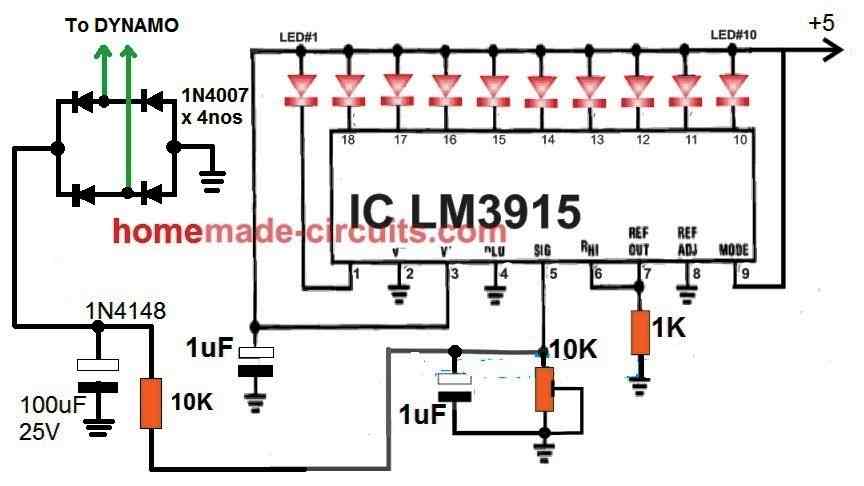
In the above figure we can see how the IC LM3915 is wired to convert the voltage variations from the dynamo into a sequencing LED bar graph display.
At low speeds only a few LEDs on the left side will be illuminated, and as the bicycle speed increases more LEDs will start illuminating from left to right, until all the LEDs are illuminated at the maximum bicycle speed.
The 10K preset can be adjusted to calibrate the range of the LED bar graph, such that all the 10 LEDs illuminate only when the bicycle is moving at its maximum possible speed.
If you want to have a fixed resistor in place of the 10K preset, then you can use the following resistive divider formula to calculate its value:
Vout = Vin x R2 / (R1 + R2)
Here, R1 is the value of the 10K resistor shown at the lef side of the circuit
R2 is assumed to be the fixed resistor in place of the 10K preset.
Vout is the maximum voltage required at pin#5, which is supposed to 200mV or 0.2 V.
Vin is the maximum voltage from the dynamo which is supposed to generate the 200mV at pin#5 of the IC.
How the Circuit Works
To use this LM3915 based bicycle speed indicator circuit you will need to have a dynamo installed on your bicycle.
Next you will have to connect the dynamo wires with the bridge rectifier of the circuit as shown in the above diagram.
The bridge rectifier is required since the output the current from the dynamo is an AC ( alternating current) which needs to be converted to DC before applying to the LM3915 circuit.
After the dynamo AC is rectified it is fed to the pin#5 of the LM3915 for the necessary sensing via a 10 K preset.
The 10K preset works like a voltage divider network and makes sure that the maximum DC from the dynamo is appropriately scaled down to 200 mV, because the LM3915 is internally configured to sense a maximum range of 200 mV at its pin#5.
When a maximum of 200 mV is detected at pin#5 of the IC, all the outputs of the IC become active which means all the connected LEDs will light up.
How to Calibrate
As discussed above the 10K preset at pin#5 of the IC can be used to calibrate the circuit in the following manner.
Put your cycle on stand and start paddling at the maximum possible speed.
Simultaneously, adjust the preset so that at the maximum bicycle wheel rotation the 10th LED just begins illuminating.
Now, if you reduce the paddling speed you should see the LEDs slowly shutting off one by one to settle at some lower level, depending on the paddling rate and the corresponding dynamo voltage.
If you slowly reduce the paddling speed to minimum, that should cause all the LEDs to almost shut off completely.
Using Magnetic Sensor
Now I have explained how the magnetic sensor based design can be implemented to measure the bicycle speed over a given meter.
The following image shows how the magnet and the hall effect sensor or the reed switch sensor can be installed on the front wheel and fork of the bicycle. The magnetic sensor can be a hall effect sensor or a reed switch.
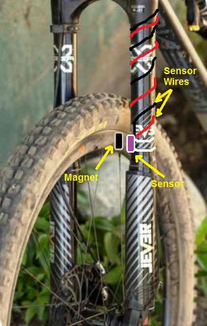
Referring to the above figure, we can see that a permanent magnet is fixed on the wheel frame, while the sensor device is fixed on the fork of the bicycle.
Both the elements are fixed face to face such that on each wheel rotation the magnet and the sensor cut each other, causing the magnetic field of the magnet to cut through the sensor.
This means that on each full rotation when the magnetic field cuts through the sensor, the sensor is able to respond to this and generate a corresponding electrical pulse at its output.
It means the pulses from the sensor will be at the same rate as the number of rotations of the wheel.
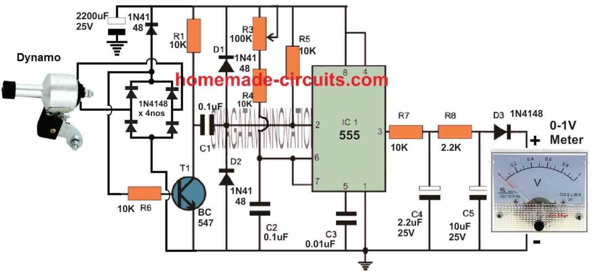
These pulses can be processed through a 555 monostable circuit and fed to a meter to get the proportionate speed reading on the meter. This design is shown in the following figure:
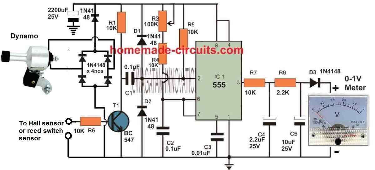
As the wheel rotates, the hall effect is triggered by the magnet on each rotation of the wheel. This causes an electrical pulse to be generated at the output of the hall sensor which is fed to the base of the BC547 transistor.
The transistor switches ON/OFF accordingly, triggering the IC 555 frequency to voltage converter, so that the pin#3 output of the 555 generates appropriately dimensioned pulses corresponding to the magnetic sensor pulses.
The rate of this pulse becomes faster and faster as the speed of the bicycle increases. Conversely, the rate of the pulses from the IC 555 output gets slower and slower as the speed of the bicycle decreases.
This varying rate of pulses at pin#3 output of the 555 is fed to an integrator circuit comprising of R7, R8, C4, C5 which appropriately convert the varying pulse rate into a proportionately increasing or decreasing DC voltage.
This DC voltage is fed to a voltmeter which translates the varying pulses into volts reading that's directly proportionate to the speed of the bicycle.
Pot R3 which can be a preset also is used to calibrate the meter such that at the maximum dynamo voltage the meter reads a full scale deflection.
Connecting the Dynamo directly with the 555 Circuit without magnetic sensor
If you think the hall effect sensor method is too complex and messy, you can directly configure the dynamo outputs with the 555 input as shown in the following diagram.
As the speed of the bicycle varies, the number the AC cycles from the dynamo also varies proportionately.
This varying AC from the dynamo is converted to DC pulses through a bridge rectifier and applied to the base of the BC547.
The BC547 in turn triggers the IC 555 monostable which converts the DC pulses from the dynamo into proportionate numbers of ON/OFF signals at its output pin#3.
As explained previously, the output from the IC 555 is applied to an integrator (R7, R8, C4, C5) which converts the ON/OFF signals into a constantly varying DC, which is finally applied to a voltmeter.
The voltmeter displays the varying DC, which is directly proportional to the speed of the bicycle.


Questions & Answers
How to build the speedometer with hall sensor and arduino uno and it should display speed, rpm and distance.
I think you can try the following concept:
https://www.homemade-circuits.com/tachometer-using-arduino/
I want to build an Anrduino-based ultrasonic circuit to detect when cars are too close (<1,5m) to my bike. In order to only activate the circuit when I'm riding above a threshold speed, I thought of using a (wired) bike computer sensor I have. How should I go about connecting this sensor to the Arduino in order to read or compute my speed through code?.
Hi, sorry, I do not have an Arduino based speedometer circuit at this moment, If I happen to design one will surely let you know.
In my digital meter I want to increase a reading 10%more than actual what I should do? KeKe 9824507537 India wattsup
There should be some preset adjustment facility in your circuit which can be adjusted to increase the range of the meter.
Not sure if I am missing something but I haven’t seen a dynamo on a pushbike for 50 years!
Yes, they are still available. Wheel-hubs with dynamo built-in are also available!
Dynamo is an optional device, you can use it bicycles if you want to apply electrical gadgets on the bike such as lights, horn etc
Yes my friend, I know that because it was the only lighting option for a pushbike when I was a child (over 60 years ago). But as I said I haven’t seen one in my country for over 50 years. I didn’t know they were still available.
OK, Got it! thanks for the feedback!
Hi, my friend!
Maybe use beam photoelectric sensor with segment display? How about the idea?
Thank you Jorge, that’s also a good idea, but the design can be a little complex to build for the newcomers.
Hi interesting but this is not a speedometer it does not tell what speed you are doing, all it tell you if you are travelling fast or slow
But never the less quite interesting
Keith
Hi, thank you, that’s correct, but the circuits can work like a speedometer once the meter scale is calibrated using an actual speedometer.
Hi sir thanks for this circuit I think it will be great idea for E bike construction
Sure Chris, this circuit can be used in E bikes as a speedometer!
Kindly make igbt protection circuit for the high frequency applications. It will be very helpful for us.
Thanks for the feedback! I will try to do it soon…