In this article we investigate an ATS circuit for initiating an automatic changeover from mains supply to generator supply through many intermediate transfer stages which involves activating the fuel valve, choke valve and the generator starter. The circuit was requested by Mr. Hari, and another dedicated reader from this blog.
Requirement for 5kva LPG Generator
I'm Hari, from Indonesia. Thank you for your circuit ideas, i made a battery charger based on your design. Right now, i'm looking for Automatic Transfer Switch (ATS) for my portable generator.
It's 5000VA LPG powered generator with electric starter. Buy ready to use ATS is very expensive, i want to make it myself. Can you help me design the ATS? Right now, i need to shut off the LPG valve manually to turn off my generator.
I have plan to add LPG solenoid valve so i can close/open the LPG supply electrically. And add mechanic solenoid (push-pull, normally pull) to automate the choke.
The ATS system feature i need are:
- detect main supply, during normal condition (when main supply on), the ATS close the main to
load connection and open the generator to load connection - when main supply off, the ATS open the main supply to load connection, but keep the generator to load connection open.
- then, the system will activate LPG solenoid valve (normally closed) to open LPG supply to the engine and activate mechanical solenoid (normally pulled) to push the choke grip to START position
- after that, the ATS will send signal to the generator starter and start to crank the generator automatically maximum for 5 seconds. If the engine fails to start within 5 seconds, the system will stop for at least 5 second before attempting to start the engine again.
- When 3rd trial fails, the system activate an alarm (it could be flashing light or sound).
- if the starter succeeds, and the generator runs, the system will wait for 10 seconds then the system will:
- deactivate mechanical solenoid so that it pulls the choke grip back to CLOSE position.
- after this, finally the system will close the connection between generator to load.
- if the main power back, the ATS will open the generator to load connection, and keep the generator run without load for 2 minutes and turn the generator off by deactivate LPG solenoid valve.
- several seconds later, the system will open the generator to load connection, it close the connection between main to load connection
Second Request
Sir in my area, we have problem of load-shading. i want a circuit (system) to automatically turn ON a self start gas generator (6 KVAR) when Light (Grid Supply) goes OFF and load should shift to generator by itself.
And when Light (Grid Supply) is back, automatically turns OFF generator and load should be connected to gird Supply..
I know a system using automatic change over and a relay. it is only to automatically turn off generator and shift to Grid..automatic change over is used to shift from generator to Grid and relay is used only to turn off generator..
Sir, please tell me a system so that we can make our task easy to turn on and turn off generator. I think there may be a system such that when light goes off load automatically connects to generator, and we use remote or cell phone to turn on generator.
And to turn off there is already an automatic system...
Design#1: Operational Details
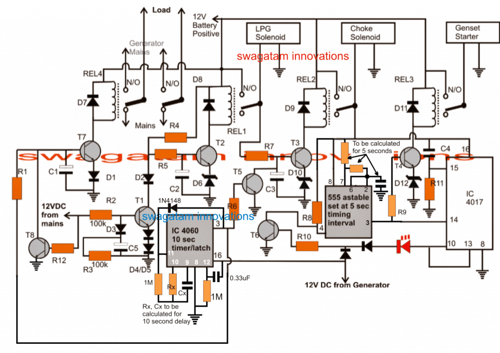
The ATS circuit or automatic relay changeover for generator/ mains circuit as shown below can be understood as follows:
For so long as home mains is present T1 base receives the rectified low voltage DC and keeps T2 base grounded.
With T2 base grounded REL1 is held switched OFF along with REL2, REL3 and REL4, the whole circuit thus stays switched OFF.
With REL4 deactivated, the DPDT holds the home mains supply with the load and the load gets powered via its N/C contacts.
Now in a situation when home mains fails, T1 is inhibited from its base drive and it instantly stops conducting.
With T1 OFF, T2 now activates, switching ON REL1, which in turn activates the LPG solenoid valve for allowing the fuel to reach generator combustion chamber.
After a few seconds delay T3/REL2 also activate pushing ON the choke solenoid into start position. The delay may be fixed by the tweaking the values of R7, C3.
REL2 activation switches ON the 555 astable which starts counting upto 5 seconds and triggers T4/REL3 so that the generator starter motor begins cranking the gen.
The astable allows this to happen for 5 seconds, if the generator starts, a 12V supply from a 12V adapter connected at the output of the generator feeds T6 base and disables the 555 astable.
The above 12V from the gen also activates the 4060 timer/latch which counts for about 10 seconds after which its pin#3 goes high.
The pin#3 high pulse latches the IC and also feeds T5 which deactivates REL2 so that the choke solenoid is pulled back to "close" position.
The 4060 output also simultaneously activates T7/REL4 making sure that the load now gets connected to the generator AC via N/O contacts of REL4.
Now suppose due to some fault, the cranking of the generator starter fails to initiate the generator, the astable makes three attempts with 5 seconds interval between each try.
Since the above pulses also reach IC4017 counter, after three pulses the IC4017 output sequence reaches its pin#10 which instantly latches itself due to a high at pin#13, and also disables the 555 astable by grounding its reset pin#4 via T6.
REL3 now stops feeding the crank mechanism.
An additional transistor driver/RELAY may be configured with pin#10 of IC 4017. The N/O contacts of this relay then could be wired with an alarm for the required warning in case the cranking attempts fails to start the generator.
When mains AC returns, T1 receievs the atached 12VDC at its base, however due to the presence of R2, D3, C5, T1 is restricted from the base voltage for a few seconds, until C5 charges.
In the meantime T7 is disabled and REL4 reverted to home mains position by T8, this happens as soon as mains returns, so that the generator gets immediately unloaded from the connected appliances.
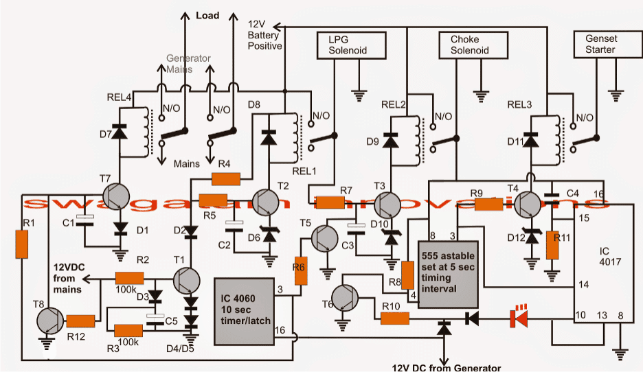
Parts list for the above automatic transfer switch or ATS circuit
R1, R4, R5, R6, R7, R8, R9, R10, R11 = 10K
R2, R3 = 100K
C4 = 0.1uF
C1----C5 = timing capacitors, can be between 10uF to 100uF
All transistors are BC547
All rectifier diodes are = 1N4007
All zener diodes (D6, D10, D12) are = 3V, 1/2 watt
REL1---REL3 = 12V/10 amps/400 ohms
REL4 = 12V/40amps or as per load specs
IC 555 Astable Configuration
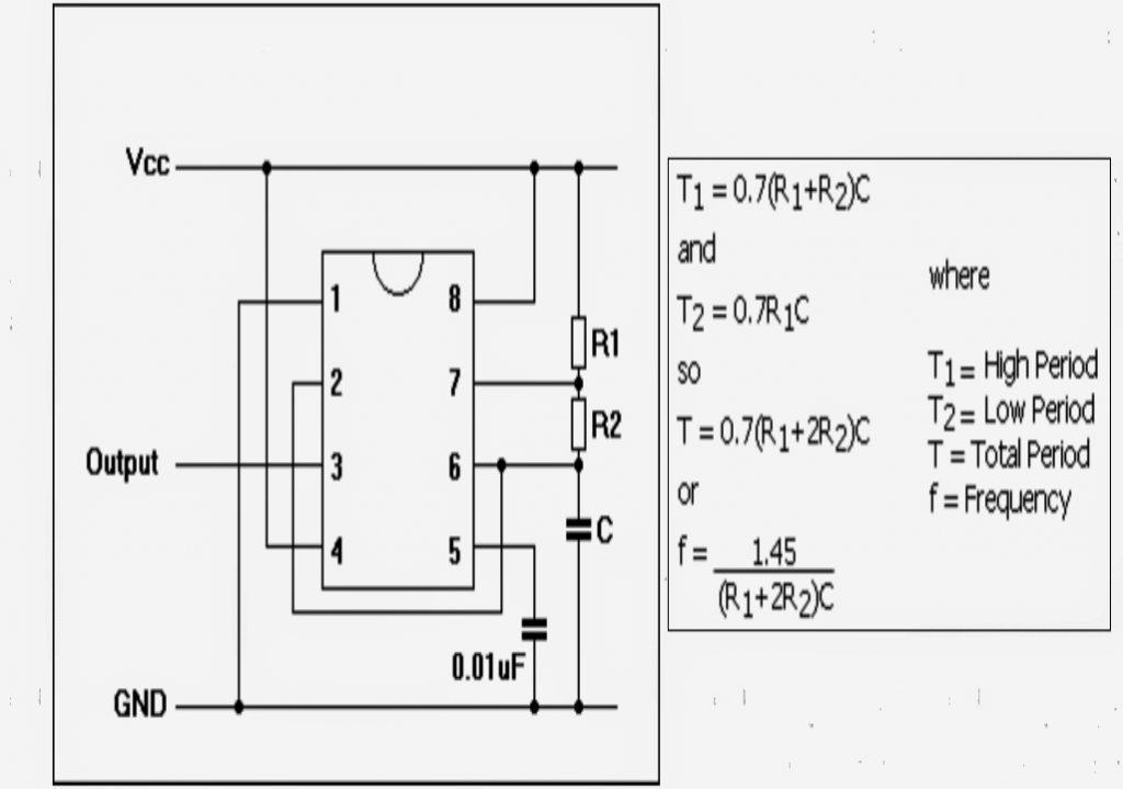
IC 555 Astable Frequency Formula
f = 1.45 / (R1 + 2R2)C
The following formula can be used for calculating the high time and low time periods or the ON/OFF time of the IC 555 astable:
On Time T1 = 0.7(R1 + R2)C
OFF Time T2 = 0.7R1C
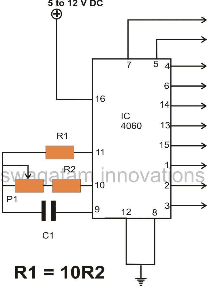
IC 4060 Timer Calculation and Formula
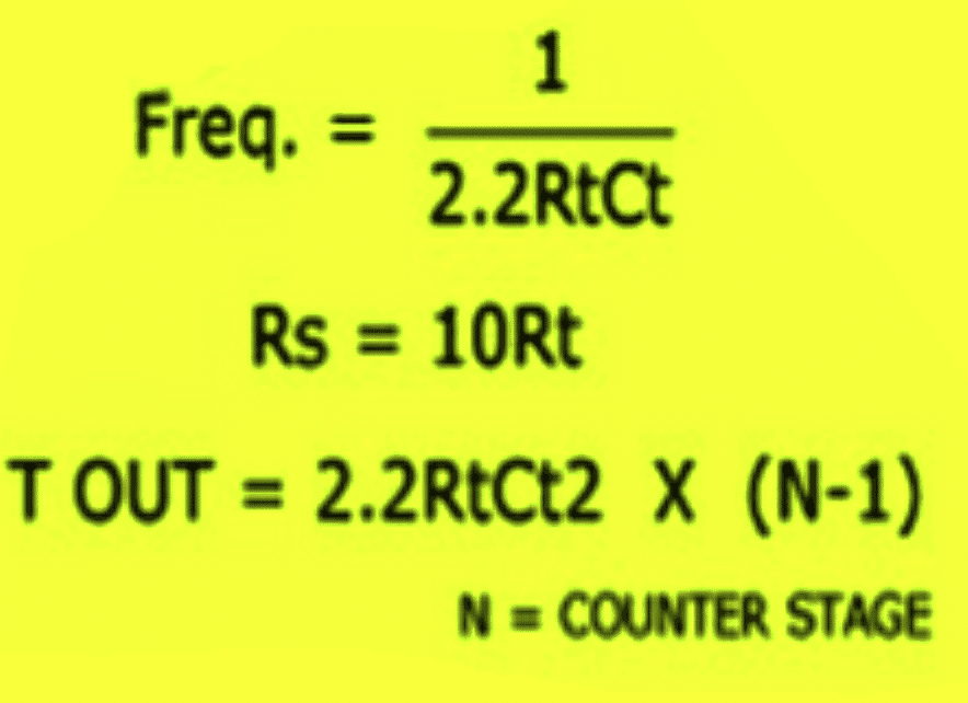
or you can also use the following formula:
f(osc) = 1 / 2.3 x Rt x Ct
2.3 is a constant term which will not need any change.
The oscillator section inside the IC will be able to give stable output only if the following criteria is maintained:
Rt << R2 and R2 x C2 << Rt x Ct.
Updated ATS Circuit Diagram with complete IC 4060 and IC 555 wiring details
Design#2
In the following post I have explained an enhanced Automatic Transfer Switch (ATS) Circuit, which includes several customized sequential changeover relay stages making the system truly smart!
Designed and written by: Abu-Hafss.
Main Features
The circuit presented here is an ATS with following features:
a) Battery Voltage Monitor - The system will not operate when the battery drops to a certain preset level.
b) In the event of power failure, the generator engine will be cranked after 5 sec. The cranking cycle will be 2 minutes in which there will be 12 cranks of 5 sec. each with an interval of 5 sec.
c) As soon as the engine is started, the cranking will be stopped.
d) Initially the generator will start on PETROL and will shift to GAS after 10 seconds.
e) When Grid Mains is restored the load will be shifted to Mains immediately but the generator will be switched off after 10 sec.
Circuit Diagram
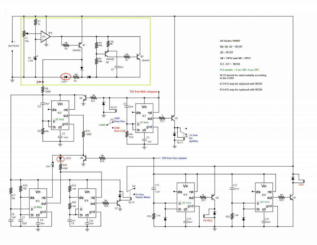
CIRCUIT DESCRIPTION:
1) The circuit enclosed in the green box makes up the battery monitor and it working may be understood here. If the generator is equipped with battery charging setup then this circuit might not be required because the battery will remain in good health. In that case, the entire circuit may be omitted and point X may be connected to the +(ve) of the battery.
2) When the Grid Mains goes off, the generator will be supplied with 12V via relay RLY1 for ignition i.e. RLY1 acts as an ignition switch and RLY2 shifts the LOAD to Generator 220V (which is not yet generated). The absence of grid Mains will switch off Q4 and as a result BATT 12V will be supplied to the rest of the circuit.
IC2, which is configured as "Power-on delay Timer" causes a delay of 5 sec and then resets IC3. IC3 is configured as self-triggering monostable having ON period of about 2 minutes. IC3 resets IC4 which is configured as an astable vibrator (about 5 sec ON and 5 sec OFF). During 2 minutes, IC4 cranks the generator (via R20/Q7/RLY3) 12 times for 5 sec with an interval of 5 sec.
If the engine does not starts within 2 minutes, LED2 will glow to indicate engine fault and the entire system will come to halt until the Grid Mains is restored. If required, the cranking procedure can be restarted by pressing the (Push-to-Off) reset button SW1.
3) Now, assuming that the engine has started during cranking, the generator will start producing electricity hence, 12V from generator adapter will be available. This will switch on Q6 hence, IC3 and IC4 will be powered off which ultimately stops the cranking cycle.
4) The 12V from generator will also power on IC5 and IC6. Both are configured as "Power-on Delay Timer" for about 10 sec and 20 sec respectively. For the initial 10 sec Q8 will conduct and the solenoid valve for PETROL will be opened to supply petrol to the generator. After 10 sec Q8 will stop conducting thereby stopping the petrol supply.
The engine will continue to run on petrol which present in the fuel lines. After about 10 sec the output of IC6 will become high and Q9 will start conducting. This will switch on the solenoid valve for GAS hence, the engine will now continue to run on gas.
5) Now, assuming the grid mains is restored, the 12V from mains adapter will switch on relay RLY2 which will switch the load immediately to the grid mains. The mains 12V will also switch on Q4 hence, IC2, IC3 and IC4 will be disconnected from the battery 12V.
The 12V mains will also power on IC7 which is configured as "Power-on Delay Timer". The output of IC7 will become high after about 5 sec which will switch off Q5 and de-energize RLY1, ultimately the 12V for generator will be switched off and the generator will be stopped.



Questions & Answers
Hi Swagatam sir,
wish u &ur family a Happy Diwali…may god bless u…
Hi Sanatan,
Wish you too a Very Happy Diwali!!
Hi Swagatam,
Thank for your effort to help us. I'll try to make it.
Warm regards,
Hari
You are welcome Hari
No…that's not feasible.
Hello sir,
Wish u and ur family a very very happy dipawali .
Hello Avijeet
Wish you too and your family a Very Happy Diwali.
Hello sir,
Actually I want to make remote switch using ht12e, ht12d,rf 434mhz tx and rx but this all are not available in my local market.if u suggest me some sites who sells good quality products and reliable in products delevery .this will help me a lot.
Thanks
6V4AH will support at the most two mobile phones, and will need recharging after a single charge of the two mobile phones.
please tell me about ic 4060 there is only two pin use pin 3,16circuit ic 555 circuit there is no nagative line is connected and and ic 4017 i do not understand plz email me
set the rest of the pins as shown here:
img.bhs4.com/ca/6/ca6021e3fd1d873281438d1bf721ef4e27ceaa0b_large.jpg
use R1 = 1meg
R2/R3 = set for 10 seconds
C1 = 0,22uF
555 and 4017 remaining pins are configured as per their standard connections, check their datasheets.
Sir,
Can you please provide me the schematic for 555 and 4017 connection or datasheet.
I am much interested in that circuit.I will make that one and provide you the feed back.
Syed, I'll try to update the article with the required diagrams soon…
Please update it..
Done!
Pls can you update the circuit about 4017 & 555 ,Thanks.
pls sir can the circuit be use with a remote
pls help me sir am in need of it
pls sir can the circuit about automatic electric switch using arduino
Need to know how to mod ur ATS to fit 3 phase 220/440 home supply to work with single phase genset supply? Cheers!
did anybody build this circuit to to test if all the components and circuit is working properly
thanks
Nobody???
Sir plz can you upload a circuit diagram of generator start circuit which start the generator on petrol and then shift it to Gas/LPG.
Junaid, I will try to do it soon, can you provide some more details regarding the application, would help me to design it in a better way.
Sir sorry for late reply….! sir i want to make my generator automatic start on petrol then shift the generator on gas and finally turn on the load and when main supply comes it will auto shift the load to main and turn off the generator..in short i want to use this circuit with automatic ATS for my generator which is placed on 2nd floor. i will very thankful to you if you upload the circuit diagram as soon as possible
thanks Junaid, but an automatic start will require a specific mechanism, I won't be able to design the mechanism, I can only suggest the relay switching circuit,
sir its fine for me my generator is already button/self start.i think that relay will do the job (automatic start) but my main purpose is that the generator should start on petrol then after 10 to 15 second automatic shift it to the GAS/LPG..hope you will help me for this.
OK…that will require some kind of solenoid valve changeover mechanism, if possible I'll try to design.
Ok sir I am waiting for your design…please if possible make it soon. thanks in advance.
I'll try to design it soon…please stay tuned.
Junaid, I have published the idea here:
https://www.homemade-circuits.com/2015/08/petrol-to-lpg-ats-using-solenoid.html
Thanx for uploading the circuit diagram i really appreciate your effort….
What should the value of resistor in 4060 ,R1 ,R2 ,P1?
R1 can be 1.5 meg….R2 = 10K…P1 = 1M pot
Good day Swagatam. I have build this circuit quite some time ago and gone as far as to get a PCB made by a local manufacturer. The circuit works brilliantly but I need to note the following. When the mains AC returns, relay 4's coil remains energized. Relay 4 never switch back to mains power. I have terminated T8 emitter to ground with a diode that solved the problem but the switch back to mains power is instantaneous with no delay, the delay is crucial not to damage any electronics with the switch back. Can you comment and advise what can be done to solve this as the original configuration of T8 emitter to pin 3 of 4060 does not work. Thank you for the great website. Not many people do things like this for free. THUMBS UP.
Thanks very much Chris, I am glad it's working as per the expectations!
yes it seems there's a "typo"…T8 emitter must be connected with the ground and not with pin#3 of 4060….however a diode at the emitter of T8 may not be necessary, you can connect it directly to the ground line for a better response and an full deactivation of T7….
when mains returns, the rel4 response should be instant according to me, but if you think that rel4 should respond after a couple of seconds, you can implement it by attaching a resistor between the points where the collector of T8 joins with the base of T7 and the where C1 positive is connected.
This resistor value should be tweaked along with R1 value such that together they do not hamper the Rel4 activation current specs, and allows REL4 to operate normally.
another point that requires to be corrected is the IC 4060 resetting back action when mains returns.
This may be done by connecting pin12 of the IC to grounds via a 1M resistor, and then connecting a 0.22uF cap across pin12 and the 12V from the mains adapter supply 🙂
I hope I could explain the mods clearly:) If you have further doubts please do let me know!
cheers!
Hello Swagatam, am also interested in the automated change over switch. Your assistance to Chris Cloete has been immensely useful and I think that you will give me a more updated circuit now with reference to the assistance you has been given to Chris. Please may you help me with the correct updated circuit for I want to design the circuit. I will be much grateful if my request is given an immediate attention. Thanks in anticipation.
can we delay the circuit for 1-3 min to make sure that the power is off before we start the generator
you can do it by removing D3 and connecting C5 directly to the base of T1….but this will also mean an equal amount of delay for the change over when mains returns
Have somone made this circuit?
hi swagatam
do you have an ats circuit like this that works from a pic16f876a or similar
thanks
sorry I do not have it at the moment…
Hi Swagatam. Love your work. Have you done one for a standalone? I'm looking for something to start a petrol engine driving a car alternator(s) to help with large loads in the day, and run the lights/fridge into the evening. I have 600w solar, large battery bank, and 3000/6000 inverter. I was thinking seriesed relays (cheap). One no/nc with n/c switched over to n/o at low bat voltage (resisted load), through the next relay, which is controlled by (resisted load, diode blocked) alternator current to switch starter off once engine starts. Then a third relay controlling ignition spark(n/c), opened once bat voltage level has got to optimum peak?
Any chance that would work?
Maybe a low voltage starter bat (separate bat) relay/resistor circuit, so it doesn't keep winding if there's a fault?
I could incorporate a 555 timer, or similar to limit excess starter winding on fault, yes, and a vacuum or centrifugal choke control, but I thought I would run it by you anyways.
Your expansive genius and massive inventory means I thought it best to ask rather than search your many circuits.
Cheers., Tim.
Thanks Tim,
Yes that's possible…Basically what you need is a low battery cut-off relay circuit that would changeover from battery to alternator (through a petrol engine) as soon as a low battery is detected specially during night…and should also cut off the ignition for the engine once the battery is fully charged back to the optimal level.
but I could not correctly understand what you meant by the following sentence:
"Maybe a low voltage starter bat (separate bat) relay/resistor circuit, so it doesn't keep winding if there's a fault?"
Can you elaborate on this a little more….
Dear sir I have an problem, I have a submersible in my house but in my house there are two seperate electric connection because of two partitions , I want to operate my pump from both connections by separate switches for separate connection please help me
Dear Sahil, for this you will need a set/reset relay circuit installed at the two sources and wired in parallel with the motor.
the set reset relay can be made as shown below:
2.bp.blogspot.com/-KaxQesNmH9A/U9cglC_i64I/AAAAAAAAHu4/XS-uqmtWlrk/s1600/set+reset+circuit.jpg
hey hi
Your stuff is great. I have a dual 555 timer circuit for a treadmill MC-2100 PCB and it will not function correctly. The trimmer is a 10K while the pin 7 resistor is 22K. After a few seconds the motor starts at 50+ rpm and takes off with no effect from the 100K speed pot. What is going wrong. Triple check circuit and components. Need help desperately as a customer is waiting.
connect a small 12V flashlight bulb with pin#3 and ground and check whether the light is varying its intensity or not in response to the 10K adjustments… this will confirm if the IC 555 is faulty or the treadmill IC??
hie, thankyou for helping and you are doing great job. i wanted ask you about how to switch the power of solar cell into battery in night time while making smart stcik for blind people and interfacing it with atmega 8
Hi, thanks you, you can do it with the following example circuit
https://www.homemade-circuits.com/2013/03/simplest-automatic-led-solar-light.html