• Skip to main content
  • Skip to primary sidebar

Homemade Circuit Projects

Need circuit help? Post them in the comments! I've answered over 50,000!

Blog | Categories | About | Contact | Calculators-online
You are here: Home / Water Controller / Submersible Pump Start/Stop Circuit

Submersible Pump Start/Stop Circuit

Last Updated on November 24, 2019 by Swagatam 103 Comments

In this post I have explained an automatic submersible pump start, stop circuit with dry run protection in order to implement an automatic ON/OFF switching of the motor in response to the high/low water levels of the overhead tank.

Table of Contents
  • Circuit Concept
  • Circuit Operation
  • Parts List

Circuit Concept

In one of the previous posts I have explained a similar concept which also dealt with an automatic start/stop function of the submersible pump contactor button, however since here the sensors involved float switches, the design looked a bit complex and not suitable for everyone.

Moreover, the dry run protection included in the design relied on the temperature change of the motor for executing the required protection of the motor. This feature too was not too desirable for a layman since installing the heat sensor over the underground motor was not easy.

In this post I have tried to eliminate all these hassles and designed a circuit that is featured to sense the water presence solely through metal sensors immersed in the relevant water sources.

Circuit Operation

So I have explained the proposed Automatic submersible pump start, stop circuit with dry run protection.

warning message: electricity is dangerous, proceed with caution
Automatic submersible pump start, stop circuit with dry run protection

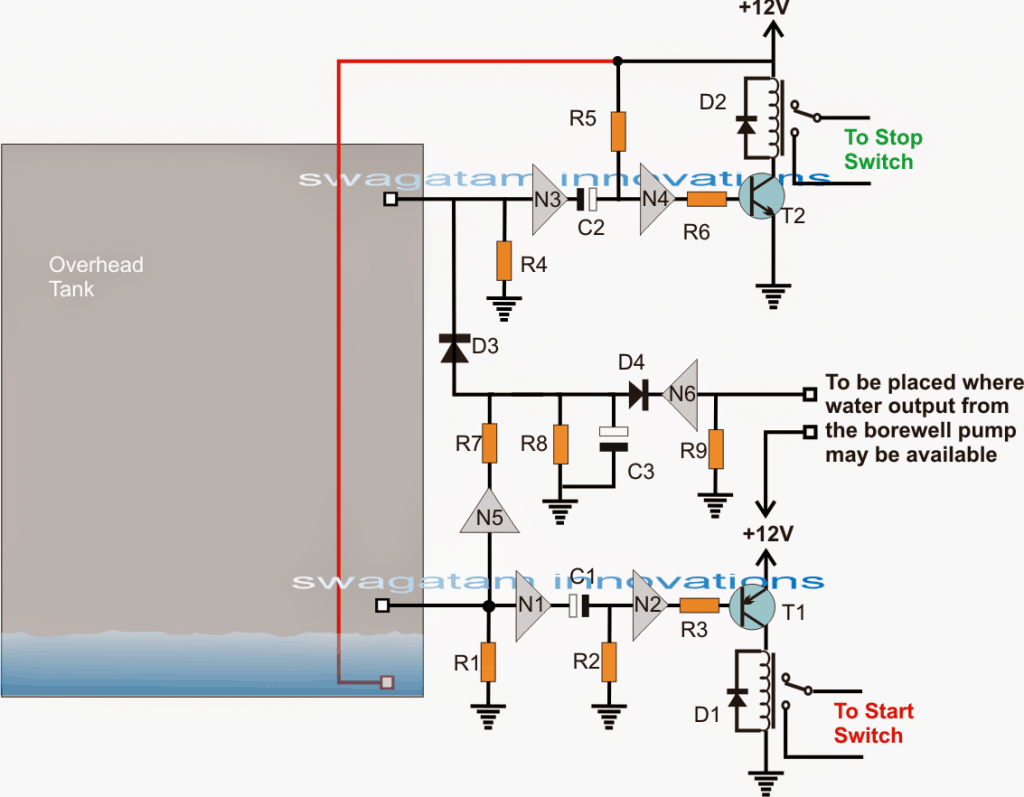
A single IC 4049 can be seen engaged for the entire sensing, start stop actions and the dry run protection execution.

The gates involved here are 6 NOT gates from the IC 4049 which are basically rigged as inverters (for inverting the polarity of the fed voltage at its input).

Let's assume the water inside the over head tank goes below the desired lower threshold, as indicated in the above diagram.

The situation removes the positive potential that ws supplied through the water to the input of N1. N1 responds to this by causing a positive to appear at its output pin, which instantly causes C1 to begin charging via R2.

The above condition also allows the positive from the output of N1 to reach the input of N2, which in turn produces a low or a negative at the base of T1 via R3....the associated relay now toggles ON and activates the "START"  button of the contactor....however the relay activation is sustained only for a second or so until C1 is fully charged, this length may be set by appropriately tweaking the values of C1/R2.

For the moment let's forget about N5/N6 stage which are positioned for the dry run protection implementation.

Let's assume the pump is running and pouring water into the shown OH tank.

The water now begins filling inside the tank, until the level reaches the brim of the tank "kissing" the sensor corresponding to the N3 input.

This allow a positive through the water to feed the input of N3, enabling its output to go low (negative), which instantly causes C2 to begin charging via R5, but in the process the input of N4 also becomes low and its output inverts to a high prompting the relay driver to activate the relay.

The upper relay instantly activates but only for a second, toggling the "STOP" button of the contactor, and halting the pump motor. The relay timing may be set by appropriately tweaking the values of C2/R5.

The above explanation takes care of the automatic water level control by toggling the submersible start/stop button through the circuit's relays. Now it may be interesting to learn how the dry run protection is designed to prevent a dry run hazard in the absence of water inside the borewell or a underground tank.

Let's go back to the initial situation when the water in the OHT has fallen below the lower threshold and rendered a low at the input of N1....which also renders a low at the input N5.

N5 output turns high due to this and provides a positive supply for C3 so that it can begin charging.

However since the process is also supposed to start the motor, if water is present, the pump may start pouring water in the OHT which is supposed to be detected by the input of N6, causing its output to go low.

With N6 output at low, C3 is inhibited from charging, and the situation stays stalemate...and the motor continues to pump water with no change in the previously explained procedures.

But, suppose the motor experiences a dry run due to an absence of water in the well....as stated above C3 begins charging and the output of N6 never turns negative to stop C3 from charging fully....therefore C3 is able to complete its charging within a predetermined span of time (decided by C3/R8) and finally producing a high (positive) at the input N3.

N3 responds to this in the same way as it would do when the water in the tank is detected at the uppermost threshold....prompting the switching of the upper relay and stopping the motor from running any further.

The dry run protection for the discussed submersible pump start, stop circuit is thus executed.

Parts List

  • R1,R4,R9 = 6M8
  • R3,R7,R6 = 10K
  • R8 = 100K
  • R2,R5,C1,C2,C3 = to be dteremined with experimentation
  • N1------N6 = IC 4049
  • ALL DIODES = 1N4007
  • RELAYS = 12V, 10AMP
  • T1 = BC557
  • T2 = BC547

You'll also like:

  • 1.  Safety Buoy Switch Circuit for Human Powered Submarine
  • 2.  5 Simple Water Level Controller Circuits
  • 3.  Car Tank Water Sensor Circuit
  • 4.  Industrial Tank water fill/drain controller Circuit
  • 5.  Cheap Semi Automatic, Tank Water Over Flow Controller Circuit
  • 6.  Simple Water Level Indicator Circuits (with Images)

About Swagatam

I am an electronics engineer with over 15 years of hands-on experience. I am passionate about inventing, designing electronic circuits and PCBs, and helping hobbyists bring their projects to life. That is why I founded homemade-circuits.com, a website where I share innovative circuit ideas and tutorials. Have a circuit related question? Leave a comment.... I guarantee a reply!

Previous Post: « Motorcycle Regulator, Rectifier Tester Circuit
Next Post: Rotating Beacon LED Simulator Circuit »

Reader Interactions

Comments

  1. Kevin says

    March 29, 2021 at 10:09 pm

    Just a note to possibly help reduce frustration: this circuit design shouldn’t be used with RO water

    Reply
  2. Mohamed farook says

    December 6, 2020 at 6:24 pm

    Thank you very much sir .I will try it .

    Reply
  3. Mohamed farook says

    December 6, 2020 at 9:06 am

    Dear sir , Sorry to say , My doubt is not clearly presented by me . Sir I need Buzzer sound , at the time of
    ” dry run cutoff Mode ” . Plz advise , How it possible . Thanking you .

    Reply
    • Swagatam says

      December 6, 2020 at 12:57 pm

      Hello Mohamad, if you want perfect results, then you may have to incorporate another IC 4093. Connect all its inputs pins together, connect all its output pin together. Connect the input side with C3/D4 junction, and connect the output with the positive of the buzzer, and connect the negative of the buzzer with the ground line.

      Reply
  4. mohamed farook says

    December 5, 2020 at 9:30 am

    Dear Mr . Swagatam . have a nice day . Thank u for your advise and Now the circuit working excellent .
    please give me one more advise . I need to indicate dryrun stage by buzzer . how to indicate dryrun stage ? I connecet LED between R7 to D3 anode , it affect C3 charging . and i connect buzzer + to D3 anode – to ground . its also affect
    C3 charging . Please advise me .

    Reply
    • Swagatam says

      December 5, 2020 at 9:45 pm

      Glad it is working now Mohammad, the LED or the buzzer should be connected between the +positive line and the common line which connects R7, R8, C3, D3, D4. Increase C3 sufficiently, so that the dry run is detected/activated only after 5 to 10 seconds….

      Reply
  5. mohamed farook says

    August 7, 2020 at 9:33 pm

    Mr. Swagatam , Thank you for kind reply . C3 is fully charged and 7 v only acroos C3 . this same volt reach input of N3 . at the moment N3 output not low . (near + 5v in N3 output ). I try to decrease the R7 value to 15 k , C3 fully charged and Near +10 v reach to N3 input . still the N3 out put NOT low and Stop relay NOT triggered . I change the IC still the problem continue . PLz refer approx value of C3, R7, R8 , dryrun for 90 seconds in 12 v circuit . plz Advise me where is my fault .
    thanking you .

    Reply
    • Swagatam says

      August 8, 2020 at 9:21 am

      Mr. Mohamed, the 7V was due to wrong potential divider calculation for R7/R8. It became 10 V since you reduced R7, so it is fine.

      But, at 10 V at the input of N3, its output should have turned 0 V. Please connect an LED with a 1K series resistor across N3 output and ground. When the N3 input turns 10V, this LEd Must shut off.

      Alternatively try replacing the IC with Schmitt trigger NOT gate IC such as IC 40106

      https://www.ti.com/lit/ds/symlink/cd40106b.pdf?ts=1596858654249&ref_url=https%253A%252F%252Fwww.google.com%252F

      Reply
  6. Mohamed farook says

    August 5, 2020 at 10:32 pm

    Dear mr ,Swagatam .
    I try to assembled the circuit submercible pump start stop circuit . Its on and off working is fine . but the dry run is not working properly . In 12 v circuit when the water absence , the c3 is start charging ,but finaly not producing high volt to N3 input . its only
    5v to 7 v reach the N3 input at the moment N3 logic not working and no dryrun cut off . what is the reason ? I used R 7 is 68k and
    R8 is 100 k preset . please reply , Thanking you .

    Reply
    • Swagatam says

      August 6, 2020 at 11:24 am

      Dear Mohammad, when C3 charges fully, a voltage equal to 12 V will be developed across the C3. This voltage will reach the input of N3 through D3, and will prompt N4 to switch the STOP relay.
      Please check and verify this voltage across C3, and make sure this reaches at the cathode of D3.

      Reply
  7. sudip biswas says

    February 14, 2020 at 12:24 pm

    dear Swagatam, i have connect this circuit to 9v battery so it works very good, but when i connect it with 12v 500mA small smps (available in the market) then the ic is damaged.
    what to do ?
    or how i connect the circuit with small smps (if you have circuit diagram with component list) that deliver proper current to the circuit ?

    i have lost 4 number of ic for that reason.

    Reply
    • Swagatam says

      February 14, 2020 at 6:04 pm

      Thanks Sudip, that means your SMPS is not 12 V, because the IC 4049 is rated to handle up to a maximum of 18 V, so 12 V should not be a problem at all. If in doubt you an add a 7812 IC in the middle to make sure nothing burns.

      Reply
  8. sudip biswas says

    February 7, 2020 at 1:37 pm

    very nice project sir, thanks for the circuit . but i found problem ,
    1. when switch on the circuit using 9v bat, the start and stop function work for a msecond.
    2. when the lower prob is not connected the motor on – is ok, but forwarding when it touches the lower
    prob again the stop signal on for a while.
    what to do ?
    3. if i am use to power up this circuit with 12vdc 500 mA smps, is it ok with this ?

    Reply
    • Swagatam says

      February 7, 2020 at 4:26 pm

      Thank you Sudip,
      1) I don’t think that’s possible, yet still you can prevent this by connecting 10uF/25V across base/emitter of both the relay transistor. For BC547 capacitor negative lead will go the emitter, for the BC557 the positive lead of the capacitor will connect with the emitter.
      2) That again looks impossible, because when the water rises and touches the lower probes, the N5 input will become positive, which will cause its output to turn negative or 0V, this 0V will reach N3 input which is already 0V through R4, thus effectively turning N4 output to be 0V so that BC547 can never conduct.
      3) yes 12V is recommended for this circuit with 12V relays.

      Reply
      • sudip biswas says

        February 10, 2020 at 1:26 pm

        thanks sir, i have made a mistake , but it is working good.
        now i want to know that is this circuit is also capable to run a jet pump also ?
        i want it with a single switch, that means when the switch on in either direction the two different function works that is one is for submersible pump and another is for jet pump.

        Reply
        • Swagatam says

          February 10, 2020 at 5:04 pm

          Glad it’s working sudip….two function may not be possible with this circuit unless both have identical start/stop contactor ….then it may be possible…in that case the stat/stop switches could be interchanged for the two operations

          Reply
    • sandeep says

      June 28, 2020 at 7:26 pm

      can u send pcb design

      Reply
    • sandeep says

      July 4, 2020 at 10:03 pm

      what r the value of R2,R5,C1,C2,C3 you used

      Reply
  9. SANJAY GHOSH says

    November 24, 2019 at 2:55 pm

    Swagatam, Few additional features are required to be added to your circuit, which are as follows:- 1.The start switch contacts of the relay should be marked in green colour as per the switch colour of the control panel, and the stop switch contacts should be red colour. 2.For the start switch a DPDT relay would be required as many of the control panels have DPDT (4 contacts) switches fitted inside. 3.As for the stop switch NC contacts are to be used and the wires are to be connected in series with the stop switch in the control panel.

    Reply
    • Swagatam says

      November 25, 2019 at 8:08 am

      Thank you Sanjay, I hope the readers will note this and proceed accordingly. Yes the stop switch needs to be a push-to-OFF type, therefore the N/C must be used for deactivation.

      Reply
  10. SANJAY GHOSH says

    November 7, 2019 at 7:59 pm

    Swagatam, I tried the modified uln2003 circuit once again, but with the same result the relay latches on as soon as the power is switched on. This time I powered the circuit without connecting the 2003 section and I connected a 10mf capacitor across the BC547 base & emitter. The relay still latches on as soon as the power is switched on.

    Reply
    • Swagatam says

      November 7, 2019 at 8:50 pm

      Sanjay, first remove the 100K feedback resistor across the collector of BC557 and base of BC547. Check whether the circuit latches or not. If it latches then your transistors may be faulty, if not then your circuit is OK. Now replace this feedback resistor with 1M and check again, with 10uF connected across the base/emitter of BC547.

      Reply
  11. SANJAY GHOSH says

    November 5, 2019 at 4:58 pm

    Swagatam, I tested your modified 2003 waterlevel controller circuit today. The circuit when powered on, the relay just latches on and nothing else works at all I checked and rechecked the project but the result is same. I also connected the 1mf capacitor across the 547 base and emitter, but the result was same. Please help.

    Reply
    • Swagatam says

      November 5, 2019 at 9:01 pm

      Sanjay, The circuit will work 100% no doubt about it. Normally 1uF is enough to prevent power ON latching, I have tested and used this latch circuit in many applications. First check the latch circuit with 1uF but without connecting the ULN2003. If it still latches then increase the 1uF to 10uF and check again.

      Reply
  12. SANJAY GHOSH says

    November 5, 2019 at 7:17 am

    Swagatam, In submersible pumps, since the high current contacts are controlled by a contacter I feel we can use 5 or 7Amps rated relays for the start and stop switches. Please clarify.

    Reply
    • Swagatam says

      November 5, 2019 at 7:47 am

      Yes, to operate a contactor you can any low current relay.

      Reply
  13. SANJAY GHOSH says

    November 5, 2019 at 6:50 am

    Swagatam, some queries relating to the uln2003 circuit, 1.Why do we have to use extra transistors whereas pin 10 can drive the relay easily. I suggest that to switch off the relay at cut off stage use pin 16 out to put pin 7 to low state, so as to switch off the relay. Designing the circuit is beyond my capacity, I leave the job to you. Thanks.

    Reply
    • Swagatam says

      November 5, 2019 at 7:46 am

      Sanjay, the transistor circuit is for latching the relay, if you connect the relay directly the relay will deactivate as soon as the water level drops even slightly below the top level of the tank.
      I have given you the appropriate design, so you can test it now to verify the result.

      Please make sure to add a 1uF capacitor across the base and emitter of the BC547 otherwise the relay will latch as soon as the circuit is powered.

      Reply
  14. SANJAY GHOSH says

    November 4, 2019 at 9:26 pm

    Swagatam, can you design a circuit diagram of a waterlevel indicator, where the indication should be on a common cathode 7 segment display. The circuit should also include a pump controller with municipal water supply pipeline sensor and a overflow cutoff with a single relay.

    Reply
    • Swagatam says

      November 5, 2019 at 11:54 am

      Presently I do not have it, I’ll try to design it and let you know.

      Reply
  15. SANJAY GHOSH says

    November 2, 2019 at 8:58 am

    Swagatam, Can the relays be replaced with Triacs? if possible please suggest the required changes in this circuit. In another circuit I am using ULN 2803 Ic as waterlevel indicator and relay driver to control the two relays for switching the pump on and off, the circuit is functioning well, I have used pin 11 of the Ic to detect water at sump and switch on the relay and pump, and pin 18 to switch off the Overhead tank relay and pump. Can you suggest some modification to do this using only a single relay?

    Reply
    • Swagatam says

      November 2, 2019 at 12:26 pm

      Sanjay, sorry triacs won’t work as far as I understand. No other option other than relay contacts will work correctly.

      For the ULN circuit you can refer to the following link, I have updated the diagram in this post.

      https://www.homemade-circuits.com/how-to-make-simple-water-level/

      Reply
  16. SANJAY GHOSH says

    November 1, 2019 at 8:40 am

    Swagatam, I would like to know whether IC HCF14049 and 4049 are the same.

    Reply
    • Swagatam says

      November 1, 2019 at 11:18 am

      yes They are one and the same..

      Reply
  17. SANJAY GHOSH says

    November 1, 2019 at 6:49 am

    Swagatam, for a 1Hp submersible pump what is the minimum rating of relay that I can use? Can I use 5 or 7amp rated relays?

    Reply
    • Swagatam says

      November 1, 2019 at 11:16 am

      Sanjay, for 1 hp motor you will need a 30 amp relay, 7 amp will not do.

      Reply
  18. SANJAY GHOSH says

    October 31, 2019 at 7:44 am

    Sir, I assembled this circuit yesterday and used a 12V SMPS supply. The project is working excellently. Thanks a lot Sir. Can you provide me the Gerber File of this circuit?

    Reply
    • Swagatam says

      October 31, 2019 at 10:24 am

      That’s great Sanjay, congrats on that! Sorry I do not have a Gerber file for the design, but any professional PCB designer will be able to do it for you…

      Reply
  19. SANJAY GHOSH says

    October 29, 2019 at 6:48 am

    Sir, I want to bypass the dry run protection section of this circuit. Please suggest the required modification.

    Reply
    • Swagatam says

      October 29, 2019 at 11:37 am

      Saurav, you can eliminate the N5, N6 stage completely to remove the dry run feature…..make sure to terminate the N5 N6 inputs to ground line since unused gate inputs must be always terminated to a logic level.

      Reply
  20. SANJAY GHOSH says

    October 28, 2019 at 11:08 am

    Sir, 4049 ic is not available in my locality, can I use cd4050 instead?

    Reply
    • Swagatam says

      October 28, 2019 at 11:45 am

      Hi Sanjay, 4050 cannot be used because it isn’t a NOT gate IC, it has buffer gates

      Reply
  21. Sanjay Ghosh says

    October 27, 2019 at 10:37 pm

    Mr. Swagatam, wish you a happy Diwali. Sir I am a simple electronics hobbyist, so please suggest some range of values of the resistors and capacitors.

    Reply
    • Swagatam says

      October 28, 2019 at 8:42 am

      Happy Diwali Sanjay, the 10K is a very standard value, but you can use any value between 10K an 22K

      Reply
    • Sagar Ch says

      August 15, 2020 at 9:29 am

      Sir, Can you please share the circuit diagram you have used to make this project as successful. Please let me know the values of R2,R5,C1,C2,C3. Kindly share the circuit diagram to this mail id

      Reply
      • Swagatam says

        August 15, 2020 at 6:27 pm

        Sagar, you can try 100k, and 10uF for the resistors and capacitors initially, and check the how much delay it generates, and then tweak the values appropriately to decrease or increase the delays…connect an LED with series 1K across the relay coil to see check and adjust the delay time visually

        Reply
        • Sagar Ch says

          August 24, 2020 at 8:45 am

          Sir I need the start relay to be ON for 2 sec and STOP relay for 1 sec. Please suggest me the values of capacitors and resistors for the above requirements.

          Are the values of R & C Directly proportional to each other or Indirectly proportional to each other?

          Reply
        • Sagar Ch says

          September 19, 2020 at 11:47 am

          Can we use 10M resistors? as 6.8M resistors are not available for me,..

          Reply
          • Swagatam says

            September 19, 2020 at 5:48 pm

            10M will also work!

            Reply
            • Sagar Ch says

              September 19, 2020 at 5:57 pm

              Sir how to connect a buzzer to the dry run terminals ,so that I can get notified easily. Please

              Reply
              • Swagatam says

                September 19, 2020 at 7:32 pm

                Sagar, connect the buzzer between the positive line and the output of N6

                Reply
            • Sagar Ch says

              September 20, 2020 at 4:38 am

              Can we use the same circuit by removing one of the relay for making water pump controller for non contactor type starters (i.e on/off by MCB)? How to modify the circuit diagram for this application

              Reply
              • Swagatam says

                September 20, 2020 at 1:50 pm

                The above design is intended for momentary ON/OFF, it is not a set/reset type therefore it cannot be used for normal water level control

                Reply
            • Sagar Ch says

              September 22, 2020 at 4:14 pm

              Hi sir. As per your suggestion I have used 100k and 10uf capacitors Inthe place of R2,R5 and C1,C2,C,3. I have got the delay time of 10seconds across the Start relay. What should I do to get 2 secs? What values must be used. Please suggest me for exact output

              Reply
              • Swagatam says

                September 22, 2020 at 7:20 pm

                Hi Sagar, to reduce the delay, reduce the 10uF at C1, C2 to 2.2uF

                Reply
            • Sagar Ch says

              October 13, 2020 at 3:15 pm

              Hi Sir thanks for replying me everytime.
              I have figured out the values of
              C2=2.2uf
              R2= 100k
              STOP relay is working fine.
              Then after for R1 and C1 , I used capacitors 10uf,2.2uf,1uf and Resistors 100k ,10k in combination with them.
              I noticed that as soon as the water decreases from middle level , START relay comes to ON state, and stays in the same position ..until the water crosses the middle level .
              In practical we need a delay of 1or 2 sec. But I’m not getting that.
              Water from pump takes a minimum of 30secs to reach the tank.
              If the START relay stays in ON state for 30sec, the motor pump will be damaged.
              I didn’t understand what to do about dry run detection with some sound alert.
              I hope you understand my problem.

              Reply
              • Swagatam says

                October 13, 2020 at 6:21 pm

                Thank you Sagar, The combination of the RC delay network should be as C1/R2, and C2/R5.

                For the dry run, connect the buzzer across the positive line and the output of N6.

                Reply
            • Sagar Ch says

              October 13, 2020 at 7:14 pm

              Sorry sir I did a mistake in naming the components in my previous question.

              I have figured out the values of
              C2=2.2uf
              R5= 100k
              STOP relay is working fine.
              Then after for R2 and C1 , I used capacitors 10uf,2.2uf,1uf and Resistors 100k ,10k in combination with them.
              I noticed that as soon as the water decreases from middle level , START relay comes to ON state, and stays in the same position ..until the water crosses the middle level .
              In practical we need a delay of 1or 2 sec. But I’m not getting that.
              Water from pump takes a minimum of 30secs to reach the tank.
              If the START relay stays in ON state for 30sec, the motor pump will be damaged.
              Did I missed anything or I have to change the values of R2 and C1.
              Sir,did anyone successfully experimented this…to be the exact working project..
              If yes,
              Please suggest me the values of them Sir.

              Reply
              • Swagatam says

                October 13, 2020 at 7:48 pm

                Sagar, that cannot happen unless your C1 is faulty or there’s some other issue in your connections. C1 and R2 can be adjusted to get any delay from 0.1 second to 1 hour.

                As soon as the water level goes below the lower contact, the N1 input becomes 0V, its output becomes 12V, which passes through C1 and causes N2 input to become high, and N2 output to turn 0V, activating the PNP and the relay to switch ON….in the meantime, within 1 second C1 charges fully and reverts the situation to switch OFF the relay.

                Connect LED/1k at the outputs of N1, and N2, and check the responses yourself.

                Make sure that inside the water tank, the +12V supply is 1 or 2 inch close to the sensing contacts

                Reply
    • Sagar Ch says

      August 24, 2020 at 8:48 am

      Sir, Can you please share the circuit diagram you have used to make this project as successful. Please let me know the values of R2,R5,C1,C2,C3. Kindly share the circuit diagram

      Reply
  22. SANJAY GHOSH says

    October 27, 2019 at 4:59 pm

    Mr. Swagatam, can you help me with a circuit diagram to improve in a project, where I am using ULN 2003 as a waterlevel indicator using LEDs, l am using a relay driver design using BC547 base and +Vcc to trigger the water detection at ground level tank. I want to use the same relay (which should get turned off) when the waterlevel reaches the tank full indicator and the relay can get deactivated by the tank full indicator pin of ULN2003.

    Reply
    • Swagatam says

      October 27, 2019 at 9:27 pm

      Hello Sanjay,

      You can try the following design

      " rel="ugc">comment image

      Reply
  23. Rakesh Kumar says

    September 11, 2019 at 12:39 pm

    Hi sir,
    You have updated so many circuits over water level controller and i also need a circuit for automatic water level controller but using a single IC or single microcontroller. I have used ne555 for this but there is a problem that some time (not all the time) it starts after the power cut (electricity breakup) while its lower probes are touching the water. (Motor should start only when its lower probes are not in contact with water). If this problem can be fixed please suggest the solution or give me a circuit design using single chip (IC or microcontroller like PIC16f676).
    Thanks for your help.

    Reply
    • Swagatam says

      September 11, 2019 at 1:17 pm

      Hi Rakesh,

      Is your 555 water level controller circuit same as given in this article?

      https://www.homemade-circuits.com/how-to-make-simple-water-level/

      Please clarify this, I’ll try to solve the issue for you!

      Reply
  24. Min Khant Naing says

    August 13, 2019 at 5:51 pm

    also this. sir.
    i dunt understand why we need a delay stopping the motor? is it the time it takes to shut down the motor or is it the time how long the motor will be shut down?

    Reply
    • Swagatam says

      August 13, 2019 at 6:53 pm

      The delay is necessary to allow the motor to pump water for the sensing operation. If the delay is not given, the water will not get enough time to reach the dry run sensing input.

      Reply
  25. Min Khant Naing says

    August 13, 2019 at 4:54 pm

    can u estimate those resistors and capacitors to experiment ? my mortor will need a 5 second delay for dry run . or is there a formula i can use for them?

    Reply
  26. Vamsi says

    March 25, 2019 at 6:17 pm

    Hi sir,
    Can u please design similar to the same above circuit for borewell starter with indicating levels also..? It’ll be very useful for us if u can.
    Thanks in advance

    Reply
    • Swagatam says

      March 25, 2019 at 7:54 pm

      Hi Vamsi, I can easily provide it, but how will you install it since the tank is supposed to be a submersible one?

      Reply
  27. Lyubomir says

    July 1, 2018 at 7:32 pm

    Hello Mister,
    How can I rework this scheme so I can use it for a water tank, that’s being filled from a water supply network? I will use electromagnet valves for filling and emptying the tank.
    Thank you!

    Reply
    • Swagatam says

      July 1, 2018 at 7:45 pm

      Hello Lyubomir, you can configure the relay contacts with your valve system, however the circuit may require further modification depending upon the valve specifications.
      If the valve is a one shot open/close type then the above circuit cam be used without modification, if the valve is a spring loaded type then it might require an additional set/reset circuit

      Reply
  28. Umar says

    August 20, 2017 at 3:14 pm

    Hello!

    You are doing very good work,keep it up to serve the world.

    Can you build a circuit with these options.
    1. low/high voltage protection.
    2. Automatic Time Reset Time.When power failure during running.

    Features:
    1. Auto On with specific time interval & Auto Off when water stops on tank inlet pipe.
    2. Tank 4 Level indication.
    3. Power On/Off Switch with LED indication.
    4. Dry Run protection with indication.
    5. Motor On with indication.
    6. Tank full indication.
    7. Manual Startup.

    Reply
    • Swagatam says

      August 20, 2017 at 3:26 pm

      Hi, Thanks, Actually I already have these stages discussed individually in this website, you can refer to the various concepts through the search box and configure them together for achieving the final circuit, if you need any help please feel free to express them through comments.

      Reply
  29. sandeep says

    November 15, 2016 at 10:12 am

    Sir For single phase agricultural submersible motor pump want to design and know approximate cost of making.The thought is for self usage and help my brother..

    Requirement is Starter for Submersible 2hp Single phase motor pump.

    For above if we add dry run will it make huge difference in cost?

    To make one end to end product what would be the cost.

    Please help me sir

    Reply
    • Swagatam says

      November 15, 2016 at 1:52 pm

      Sandeep, if you are referring to the above explained circuit, it would cost you approximately Rs.100/- without the power supply

      Reply
    • sandeep says

      November 16, 2016 at 6:08 am

      Thanks for quick and helpful reply

      Swagatam Ji, Just shared a picture link with you I was explaining to create the below type of starter… Sir ji is that the same which you are talking to?

      https://drive.google.com/file/d/0B0fqLeKQHkWBNkRsNzZCVGprOEE/view?usp=sharing

      https://drive.google.com/file/d/0B0fqLeKQHkWBYjFRRFAtT2ZaaEk/view?usp=sharing

      If we want to build one such on our own and for our neighbors what would be approximate cost to make one such product. sorry to bother you..

      Reply
    • Swagatam says

      November 16, 2016 at 10:55 am

      Sandeep, no, my above circuit is supposed to be connected with your shown "start" "stop" switches so that the system becomes automatic, and manual monitoring can be avoided.

      I have no idea about the cost of your starter box, you will have to inquire it with your nearest electrical spare part dealer.

      Reply
    • sandeep says

      November 16, 2016 at 1:13 pm

      Okay swagatam ji, thanks, I thought the circuit itself work as starter. But i really appreciate your work, wonderful.

      Reply
    • Swagatam says

      November 16, 2016 at 3:08 pm

      You are most welcome Sandeep!!

      Reply
  30. Yulleg Rahardja says

    October 25, 2016 at 1:36 am

    Thank you sir now I can use this for running my Aquaponics system. I need this to make sure my sump can be pumped up to the fish tank. I have plan to run 2 system of Aquaponics using only one pump. And your circuit really helpful to make sure I can run it into my sump system.

    Reply
    • Swagatam says

      October 25, 2016 at 7:25 am

      You are welcome Yulleg,

      yes you can use the concept for your mentioned application also….it should work as proposed in the article.

      Reply
  31. Sunday Owen says

    July 16, 2016 at 5:14 pm

    good work i appreciate your kind gesture to the way you respond to question.it mean you know what your doing.

    Reply
    • Swagatam says

      July 17, 2016 at 3:02 pm

      Thank you, it's my pleasure!

      Reply
  32. Unknown says

    February 26, 2016 at 1:32 pm

    sir,
    i had built the circuit but how to increase dry run time because for going up to tank it will take some time ie 2 minutes can u help

    Reply
    • Swagatam says

      February 27, 2016 at 10:35 am

      you can increase the value of C3, or R7 or both for increasing the dry run time limit

      Reply
  33. Vamsi Krishna says

    October 7, 2015 at 9:44 am

    Dear sir,
    can you please check the circuit practically. and then tell me what should i have to do. as per your suggest i'll proceed then..Thanks.

    Reply
  34. Andrew Ayemere says

    October 6, 2015 at 6:45 pm

    I am highly impressed how u commit yourself to serve humanity this far.
    thanks u so much sir.
    thank u so much
    Andrew.

    Reply
    • Swagatam says

      October 7, 2015 at 5:53 am

      You are most welcome Andrew, I appreciate your thoughts.

      Reply
  35. Vamsi Krishna says

    October 6, 2015 at 8:54 am

    Dear sir,
    Hi, Thanks for the rply… Sir.., Actually what i get confused here about in this circuit is…, in place of R1, R4 and R9 (6m8 / 6.8 mega ohms) valued resistors are not available when i went to buy it. so, here in place of those three resistors i kept in place of each resistor a 5.6m +1m+200k = 6.8 mega ohms when connected in series way. can u pls tell me is this procedure correct or not..? and so many times by this value i tested finally yesterday itself, by changing the values of other resistors and capacitors ( C1 and R2 , C2 and R5 , C3 and R8 ) as you mentioned the above procedure. then the both Relays ( START and STOP ) are not working when i tested with sensor wires by touching and releasing.

    And the other point is going to our past discussions, previously i sent u a message like ( START RELAY is working very good but STOP RELAY is not.) that is when i have tested in the beginning. at the first time when i went to buy components for this CKT. the seller unexpectedly given the resistor value instead of 5.6m ohms he given (green,blue,green,gold,red) 5 band colour coded resistor. then it is 56.5 ohms. in place of GOLD actually it should be YELLOW code. i don't know when i purchase it. unknowingly i put the same valued 56.5ohms resistors directly and tested the circuit. at that time START RELAY is responded very fine. and at the mean time STOP RELAY is also energised continuously. after you suggested me to CHECK THOROUGHLY. then i found the above resistor is wrong value. then again i purchased 5.6m ohms and 1meg + 200k. and then i removed all the components from bread board and again i inserted with the new once. tested. both relays are not working as i mentioned in the above paragraph. and one more doubt is…the DIODES which you mentioned are all 1N4007 or leaving the relay diodes same and other diodes 1n4148 zener…? and also i don't know which are the perfect values to activate Relays in 1 sec. by changing ( C1,R2 , C2,R5 , C3,R8) can u suggest any variable resistance for three of them…?

    SIR…, this is my brief explanation about waiting for your HELP. my language is poor.. i think you can able to understand that what i written above. Thank you very much..

    Reply
    • Swagatam says

      October 7, 2015 at 3:03 am

      Dear Vamsi,

      Thank you for updating the details, it means now you have succeeded in making the circuit work, that's great.

      the sensor resistors must be at least 10 times higher than the water resistance, the water resistance is typically around 150K to 300K, so anything 10 time higher than this can be used for R1/R4.

      The timing resistor can be identified by little trial and error, use different fixed resistors and/or capacitors and check the best possible combination….a fixed resistor is recommended for ensuring consistency on the start/stop switching, preset or pot value can accidentally change and cause problems.

      you can use 1N4007 for all the diodes, nothing's critical about them.

      Reply
  36. Vamsi Krishna says

    October 2, 2015 at 9:01 am

    Dear sir,
    as u mentioned above procedure i followed accordingly but still same problem. and as u said i connected the led in between R6 10K resistor and the base of transistor.it's glowing (anode to R 10k and cathode to base of T2.) i replaced transistor and IC with the new once if suppose faulty. and i tried changing the values of R5 grater than and lesser than 10K. but still it's same problem.can u help me pls….

    Reply
    • Swagatam says

      October 2, 2015 at 4:21 pm

      Dear Vamsi, the value of R5 is only related to the ON time pulse of the stop relay, nothing more than that.

      R5 gives positive to the input of N4, therefore the output of N4 will be negative…with negative at the base of the T2 how can it get triggered, …..unless the water reaches the top and reverts the situation.

      Reply
    • Vamsi Krishna says

      October 5, 2015 at 4:13 am

      Hi Sir,
      how r u…?…..:) I'am extremely sorry sir, that i'am unable to make this circuit, i tried so many times to make it success, as u said i changed the values of C1, R2, C2, R5 and C3, R8. But it not possible to me. i understand that i cannot make anymore without your help. sir, can u pls clarify me can i put the resistance 6.6 mega ohms in place of 6M8 (6.8mega ohms) i am sorry for disturbing you… thank you for your valuable time….

      Reply
    • Swagatam says

      October 5, 2015 at 11:18 am

      Hi Vamsi, Please let me know what you couldn't understand, and where you are stuck….I'll try to help.

      Reply
    • Vamsi Krishna says

      October 5, 2015 at 3:34 pm

      Thank you very much SIR…..:) actually I'am doing all this for my parents purpose. I will always be grateful for all that you are trying to help me… Thank you very much once again…..:) awaiting for the HELP…

      Reply
    • Swagatam says

      October 5, 2015 at 4:17 pm

      It's my pleasure Vamsi,

      Please let me know what you couldn't understand, and where you are stuck….I'll try to help.

      Reply
  37. Vamsi Krishna says

    October 1, 2015 at 2:08 pm

    That's better idea for motor running indication. Thanks for suggestion Sir…:)

    Reply
  38. Vamsi Krishna says

    October 1, 2015 at 1:56 pm

    Dear sir,
    can u pls help me, i have checked the connections thoroughly and tested the above given circuit. here, when i given power to circuit, the RELAY for START switch is working very good (as soon if power supplied to circuit imagining suppose if water empty START RELAY is automatically activating for 1sec. and suppose if water in OHT in touch with both bottom wires START RELAY is not activating and if i separate both wires, it energises for 1sec.) so, by this START RELAY working very good. as per ur suggest here in place of R2 i connected a 10K resistor. and in place of C1, instead of 22uf i replaced with 470uf 25v capacitor. then START RELAY is energising for 1sec. and now here about the problem is from the beginning of testing the STOP RELAY is energised continuously when powered to circuit. actually it should not activate until water touches to upper sensor. this is my brief explanation.so, kindly i request can u check the circuit once again please…

    Reply
    • Swagatam says

      October 2, 2015 at 6:46 am

      Dear Vamsi

      the "start" relay is supposed to activate when the water is in between the bottom RED terminal and the N1 input terminal…….. that is when the positive is NOT touching the N1 input terminal through water.

      The STOP relay will NEVER stay activated permanently because R5 is connected to positive which will produce a "0" voltage at the output N4, so how can T2 energize with a 0V at its base??

      You might have something incorrect in the assembly or any of the components could be faulty or wrongly connected.

      check it again….connect LEDs in series with the base of the T1 and T2, for getting the start, stop indications.

      Reply
    • Swagatam says

      October 2, 2015 at 6:47 am

      ….please read the "warning" statement that I have mentioned just above the comment box (below)

      Reply
    • Swagatam says

      October 2, 2015 at 6:48 am

      …sorry below the comment box…in RED color.

      Reply
  39. Vamsi Krishna says

    September 30, 2015 at 2:25 pm

    Hi Sir,
    in the above circuit, can u pls tell me how to add the LED to indicate motor running status..? Thanks.. 🙂

    Reply
    • Swagatam says

      October 1, 2015 at 2:58 am

      Hi Vamsi, that would be difficult,because the relay is supposed to trigger only momentarily….you can try a neon bulb and wire it parallel to the motor supply for getting the indications….

      Reply

Need Help? Please Leave a Comment! We value your input—Kindly keep it relevant to the above topic! Cancel reply

Your email address will not be published. Required fields are marked *

Primary Sidebar

Subscribe to New Circuit Ideas

Categories

  • Arduino Projects (87)
  • Audio and Amplifier Projects (132)
  • Automation Projects (17)
  • Automobile Electronics (101)
  • Battery Charger Circuits (83)
  • Datasheets and Components (104)
  • Electronics Theory (143)
  • Free Energy (37)
  • Games and Sports Projects (11)
  • Grid and 3-Phase (19)
  • Health related Projects (25)
  • Home Electrical Circuits (12)
  • Indicator Circuits (14)
  • Inverter Circuits (87)
  • Lamps and Lights (142)
  • Meters and Testers (69)
  • Mini Projects (46)
  • Motor Controller (64)
  • Oscillator Circuits (27)
  • Pets and Pests (15)
  • Power Supply Circuits (108)
  • Remote Control Circuits (50)
  • Security and Alarm (64)
  • Sensors and Detectors (101)
  • Solar Controller Circuits (59)
  • Temperature Controllers (42)
  • Timer and Delay Relay (49)
  • Transmitter Circuits (29)
  • Voltage Control and Protection (37)
  • Water Controller (36)

Calculators

  • Battery Back up Time Calculator
  • Capacitance Reactance Calculator
  • IC 555 Astable Calculator
  • IC 555 Monostable Calculator
  • Inductance Calculator
  • LC Resonance Calculator
  • LM317, LM338, LM396 Calculator
  • Ohm’s Law Calculator
  • Phase Angle Phase Shift Calculator
  • Power Factor (PF) Calculator
  • Reactance Calculator
  • Transistor Astable Calculator
  • Transistor base Resistor Calculator
  • Voltage Divider Calculator
  • Wire Current Calculator
  • Zener Diode Calculator
  • Filter Capacitor Calculator
  • Buck Converter Calculator
  • Boost Converter Calculator
  • Solar Panel, Inverter, Battery Calculator
  • Wire Current Calculator
  • SMPS Transformer Calculator
  • IC SG3525, SG3524 Calculator
  • Inverter LC Filter Calculator

People Also Search

555 Circuits | 741 Circuits | LM324 Circuits | LM338 Circuits | 4017 Circuits | Ultrasonic Projects | SMPS Projects | Christmas Projects | MOSFETs | Radio Circuits | Laser Circuits | PIR Projects |

Recent Comments

  • Swagatam on 9 Simple Solar Battery Charger Circuits
  • Swagatam on Arduino Pure Sine Wave Inverter Circuit with Full Program Code
  • Swagatam on How Shunt Regulator TL431 Works, Datasheet, Application
  • Swagatam on Best 3 MPPT Solar Charge Controller Circuits for Efficient Battery Charging
  • Dan Biles on 9 Simple Solar Battery Charger Circuits

Company

  • Privacy Policy
  • Cookie Policy
  • About Me
  • Contact
  • Disclaimer
  • Copyright
  • Videos
  • Sitemap

Social Profiles

  • Twitter
  • YouTube
  • Instagram
  • Pinterest
  • My Facebook-Page
  • Quora
  • Stack Exchange
  • Linkedin
  • © 2025 · Swagatam Innovations