In this post I have explained how to make a sunrise/sunset simulator circuit using LEDs and just a couple of BJTs.
The idea was requested by Mr. Jerry
Circuit Objectives and Requirements
- Apparently natural daylight is best for humans in regulating our circadian rhythm. I would like to build an LED lighting circuit to control ceiling LED lamps for my darker and windowless rooms. I'm hoping for thin flat panel lamps with a nice trim could mimic the characteristics of natural daylight (as coming through a window).
- I envision a solar panel outside regulating our circuit and possibly charging a back-up battery.
- To create the change of kelvin and brightness that natural daylight has during a typical day, we may be required to use a soft-white and a bright-white LED combo to create about 1100 lumin from each lamp.
- Kelvins and brightness start low in the morning and increase towards midday then fall off as evening approaches.
- None of the companies I've seen do this any of this well imo. Some don’t have a kelvin adjustment. Other companies went Wi-FI smart bulb route, but they have timing circuits that get out of sync with the seasons and other issues.
- I'd like to make thin flat panel lamps with nice molding trim and maybe have 2 lamps per circuit. Making it to handle 1 to 4 lamps would be an ideal option, but more issues in the circuit build.
- Using a small solar panel outside and a battery/ charge circuit indoors for night time lamp use and power outage lighting.
- I appreciate any thoughts. Making just a single one lamp circuit and using simple power supply for night time use would be a great start to make lighting work this winter
The Design
As proposed, a simple sunrise and sunset simulator circuit can be implemented using the circuit shown in the following diagram:
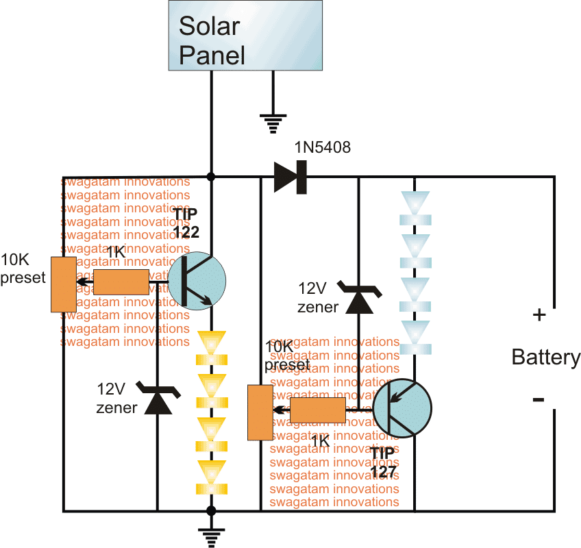
The entire circuit can be seen powered from a single solar panel for the required sunrise/sunset simulation effect on the connected LEDs.
The NPN BJT stage using the TIP122 becomes the main section of the circuit and can be expected to execute the required slow brightening of the yellow/white LEDs proportionately in response to the rising sunlight level exposed on the solar panel.
The PNP stage using TIP127 is optional and this stage is introduced to do the exact opposite of its NPN counterpart. The indicated cool white/blue LEDs are supposed to gradually illuminate and get brighter as the sunsets.
During day time, the solar panel operates the gradual brightening of the warm LEDs simulating sunrise effect, and simultaneously it also charges an attached back up battery.
When night falls, the same battery provides power to the cool white LEDs which keeps the house illuminated when its completely dark.
The battery is also under-charge protected since the 4 LEDs which are connected in series simply stop conducting as soon as the battery voltage drops below the 11V mark making sure that it does not go through a deep discharge.
For the above shown example sunrise/sunset simulator circuit using LEDs, the approximate specifications of the components could be selected as described below:
Specifications
Solar Panel: 18V, 1 amp
Battery: 12V/7AH
LEDs: 3.3V 1 watt


Questions & Answers
Hi Swagatam,
i have a suggestion, could you pls design a circuit for LED Sunrise Sunset Simulator by using 7 or 9 chips of 1W LEDs.(then I can use it with mixed colors, ex: 4 whites/ 2 blues and 1 red-(for growing plants)) All LEDs should be slowly glowing up when sunrises and stay it’s maximum brightness on day time. and slowly go off when sunset. (no need back up lights at night). I’m looking for this design for a while because I have planted aquariums. so I want to simulate a lamp as sun for my plants/ fresh water shrimps and fish. I think above circuit is also good enough if you can modify it a little with 1W LEDs,
Thanks
Pamuditha
Hi Pamuditha,

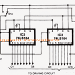
please try the following concept and let me how it goes:
Hi Swag! I came across this post and the comments below while browsing for ideas for simulating sunrise/sunset indoors (primarily for humans). I would love to learn more about this – Is the above system something you’re actually planning to build out? Do you have any recommendations for best resources to get a better grounding in the science behind the principles in your design?
Hi Sarah, I won’t be making this, but I am sure regarding its working, it will produce the results exactly as mentioned in the article.
The prnciple is simple, the transistor emitters follow the base voltage level, which is controlled by the solar panel voltage.
As the solar panel voltage increases/decreases in accordance with the sunlight, the base emitter voltage also increases/decreases at the same rate, and enables the LEDs to increase or decrease its intensity at the same rate.
Hello,
I read your post on a sunrise / sunset LED light changing circuit. https://www.homemade-circuits.com/sunrise-sunset-simulator-led-circuit/
Interestingly I am working on a similar circuit but for a very different, and arguably much more complex, project that involves weather and light changes for aquariums. At the moment the lighting system is based off 1,000 LED lights so that all colors of the light spectrum can be fairly accurately reflected based on percentage.
After having done extensive research about the light spectrum underwater I want to make a LED light that will have the correct percentages of each type of colored light so that at high sun all the lights are on and then gradually turn off again. The catch is that the blue and purple (not UV) will be on the most. At this time I have not found, nor has anyone I have contacted pointed me to, what underwater light spectrum should be at night. Of course I have no problem shutting off the lights at night, but for reasons of accuracy prefer not to do so and speculation is that blue and purple are the only colors at night – but again, no one has done the research to prove this.
This link is the best starting point for what I am describing https://manoa.hawaii.edu/exploringourfluidearth/physical/ocean-depths/light-ocean
Please note – and this is VERY important – most aquarium lights DO NOT simulate sunlight, they only use part of the light spectrum. My lighting needs to use ALL of the light spectrum for reasons of plants, fish, corals and beneficial bacteria.
If possible, I would like to do this without a microprocessor but so far have not found a decent way to implement timing control for the number of lights required for both total number and total colors.
Can you help?
Hello, to be precise white light includes all of the light spectrum, so to imitate daylight you can simply use white LEDs, and maybe some amber LEDs to imitate sun set. Blue and purple does not actually make sense as they are never seen in actual day/night cycles. Even moonlight is white in color.
If you can tell me the exact sequence of the lights, then maybe I can try helping.
Sorry for the delay, I was going to send links to explain more but then realized it was probably a waste of time.
White light – pure white light – doesn’t work for aquariums. Even when keeping my corals and using a metal hal light it wasn’t a pure white light. Often the aquarium lights are skewed in the spectrum because the light underwater reacts and interacts in a different way than in air. For example atinic bulbs are more like florescent lights in shape but emit different wave lengths to help with the growth of corals.
Fish adjust skin color based on diet and light frequencies that interact with their skin, some fish (and snakes) see much better with UV or IR light. If pure white light will work then I am all for it, however I have never had a good experience with just white light.
The light spectrum that I have mentioned, meaning the percentages of light I am looking for are based on the penetration of light underwater. Red light penetrates the least and if you are in coastal regions green light will penetrate the most otherwise its blues and purples.
The system I have designed, and this particular section of it, I will briefly explain in a moment but first…
A short history – aquariums have been in my life for years, as in since a child. At one point I owned a fish business that was based on breeding fish and then later switched to raising fish. Along the way I had to design and build my own equipment simply for two reasons – first cost and second was that most commercial systems still had to be modified to fit someones needs.
My original design of this tank ran past windows and while algae can be a problem that was solved. It started upstairs, rain down the stairs through a series of mini-waterfalls and tanks before circling the walls of the basement (prior to getting pumped back to the starting point). Water speeds and substrate were altered based on tank design and narrowing and fish of different sizes were allowed through the tank separated by rock with different size holes. The different size holes allowed the smaller fish to be escape larger fish while allowing water flow and avoiding complex building and filtering.
I moved.
So I designed a new tank system based on being in a great room – which if you don’t know what that is that is a room where the kitchen, living room and dining room are all in the same room. Its far more popular on the east coast than anywhere else.
Because of the re-design I went back to a lighting system I had before in one of my saltwater tanks that allowed lights to turn on and off to maximize light. It started with a single row on the edge of the tank, progressed in stages to turn on additional lights until the center was reached and then would start to ‘descend’ in lighting sequence to the other edge of the tank.
This tank I want to use LED lighting that is accurate to underwater ratios. I have designed and built a real wave maker (patent pending) and will be including things like a water feature that makes a mini-waterfall which in turn goes down a mock river past a small decorative village with a waterwheel etc. This water in turn goes into the tank and helps with oxygenation.
By the way, your circuit on this has a basic fish keeping flaw which I can address later later if desired. Your electronics circuit for oxygen match a similar schematic I and a friend have already built. He uses his in a car, I use mine for fish.
The LED lighting is meant to be similar to the system earlier, turns on at daylight and off in the evening with the most lights being on at high sun, however it is going to be far more in depth because I am researching weather patterns to simulate sun, overcast days, rain, storms and calm. This means that lighting will be dimmed, flicker for lightning, full strength for a calm day or run at ‘normal’ lighting.
Once the water hits the exit point of the tank, it is filtered both mechanically and biologically. Biologically with a variety of plants and water speed reduction. After this the water is heated, treated and returned back to the top of the water feature.
So what this lighting system will do is at times be a simple daylight cycle, a row or random LEDs from part of a row, that turn on at the selected dawn time (obviously in winter tropical fish need more light) and off at dark. But because of the blues, purples and greens that remain at night not all the light can go away all the time. And if you use blues, purples and greens and how much of what will depend on what is in the tank. For this reason it will be kept simple and use only three settings of deep ocean (blues and purples), partial coastal (balance of blue, green and purple) and coastal (mostly green).
If white light is dimmed but left on it will cause algae blooms and also can stress various fish and invertebrates because of not getting enough ‘night light’. Hence one of the reasons for the change in underwater lighting coloration.
Of course various chemical biologic conditions in the water can cause algae blooms as well and the real trick is to keep the good bacteria that fish need alive – which is why UV can’t be used as it sterilizes water, that and sight issues. Or more accurately, I won’t use UV to clean aquarium water.
If knowing more of the system will be helpful, or of interest, let me know.
Hi JP! I know just enough about light and photons and electricity and complex biological systems to be super interested in all of this (e.g. previously designed and built a backyard aquaponics set-up) but still very new. Your project sounds fascinating, and I would love to keep up with it/learn more as you go along – Is there a way to do that?
Very interesting indeed! Thanks for providing such an in-depth details regarding basic aquarium needs, I am sure the fishes must be so happy and feeling blessed to be in your association.
You can definitely enlighten me regarding the basic flaws that the above circuit may be having, I will try to correct it, if its feasible for me.
Do tell me if you have any specific circuit requirement or a specific algorithm for the lights, again if feasible I will try to fulfill it for you!
So after thinking for awhile about the best way to respond I think I have come up with answers for you.
The problems I saw with your circuit were not in the sense of it not working, but rather in the sense of it working to efficiently.
If you have a fish tank of typical household size and you get an algae bloom, the way to correct the problem is to either use specific filtering to clean water or to cut out light, which you do depends on the color of the algae. Algae blooms most often happen from too much light or unbalanced water chemistry.
My comment on your design being flawed wasn’t from a view of incorrect electronics, so much as it was from a view of not limiting light to a fish tank. Remember we are dealing with a closed system and not the open ocean, so water control is very different.
Most of the time we hear lots of information about how to create fish lights, but significantly less on how to LIMIT the amount of time fish lights are on. Anything over 8 hours is a question for water quality and because of that lights that rise and fall based on 8 hours are typically better. Some people even go down to 6 hours but I personally think that is over kill.
So going back to my first post about light colors and the ratio of colors, its all based on what sorts of lighting is found underwater at different times of day. Most fish lights focus on a specific spectrum to facilitate viewing or coral growth. My LED light design is to meant to implement coloring based on hitting all the different spectrum’s for different times of day. A timer starts off with a few lights and then at high sun is all lights to a slow shut down, just like sun rise and sun set. However during the lighting sequence the light spectrum is crossed.
This brings me to my second post about your circuit and it not really being complete. The flaw is not if the circuit will work, but rather that the circuit works too well. Organics in the water, potassium, hard water and a host of other features all play a part in what lives in the water and because of that, how much light the tank can handle. But if all that will happen is a simply on with dawn and off with dusk then the tank will get far to much light and will end up being over run with algae.
Also, if you are keeping things like anemones they will move around the tank to find the level of light they like the best, but that also means that you are usually pumping out a lot of heat. I had to run a 5k metal hal to get my saltwater tank corals enough light while at the same time not falling apart from corrosion. As a result there was no heater and extra cooling was in place.
Your circuit does not appear to have moisture prevention or saltwater protection built into it which, for me, is a problem because of the rapid corrosion that occurs, especially with saltwater exposure.
All this being said, I realize you didn’t design this circuit as a light for fish tanks.
If you could respond to my email I would like to go over some fish tank equipment.
Thank you for the detailed explanation. You are right, the above circuit is just for experimental purpose, it was not specifically designed for fish tanks