In this article I have explained how to make a simple and accurate autoclave heater controller circuit with timer. The idea was requested by Mr. Rajjab.
Circuit Objectives and Requirements
- This is Rajab Ali from Afghanistan. We need a circuit for controlling an autoclave for sterilization in hospital the machine works as.
- when starts cycle by pushing start button it should turn on three water heaters(30_60 Amps) after reaching 2.2 bar pressure from water steam then the circuit keep running with one heater and switch off two heaters to control pressure between 1.8 to 2.2 bar for 20 more minutes.
- If there would be any possibility to adjust the time is great.
The Design
Normally autoclaves are controlled using timers, but as per the request here the system needs to controlled by sensing steam pressure as well as through an adjustable timer.
For sensing the pressure we can use a pressure valve switch sort of mechanism for triggering the various heaters in the proposed electronic autoclave heater controller, timer circuit.
The circuit and description for the autoclave controller can be seen below:
Circuit Operation
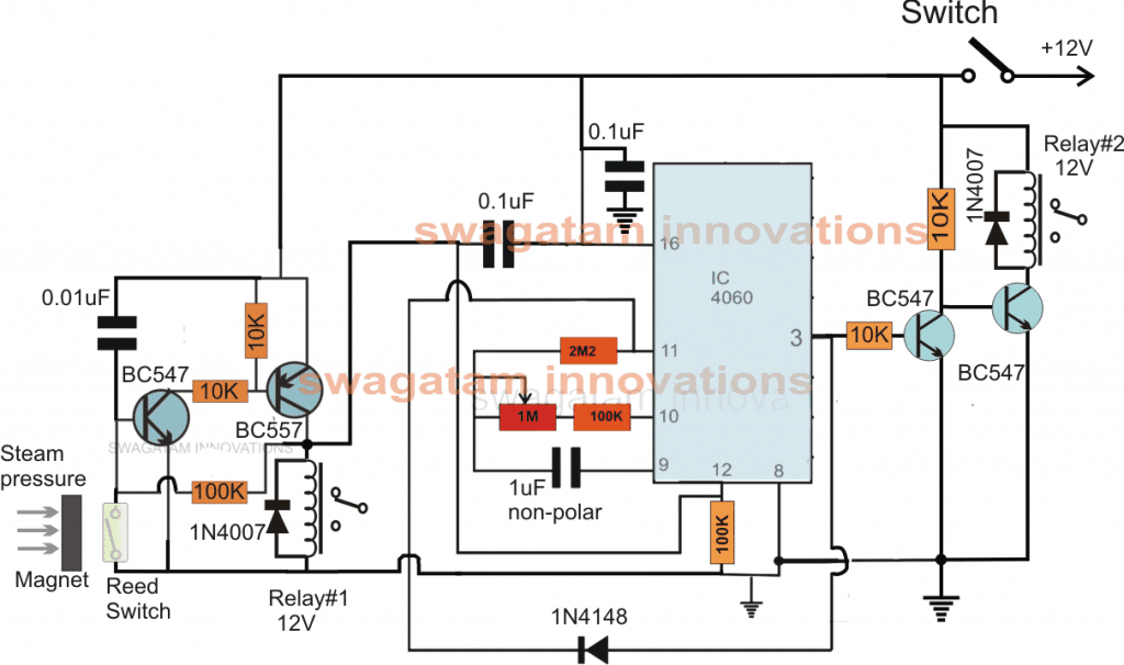
The circuit is basically made up of two sections, a transistor latch and an IC 4060 timer stages.
When the power switch is pressed or switched ON, the transistor latch circuit at the extreme left of the design is instantly toggled ON switching ON the PNP BC557.
The BC557 triggering does two things, it activates the associated relay (Relay#1) whose contacts switch ON two heaters among of the three, and next the positive from the BC557 collector blocks the pin#12 of IC 4060 inhibiting its counting action.
With its pin#12 blocked, the IC 4060 is disabled and put in standby position rendering its pin#3 inactive, and so is the connected BC547 transistor, which means the next BC547 is switched ON along with the relay. This relay (Relay#2) switches ON and becomes responsible for switching ON one of the heaters among the stipulated 3 heaters.
Thus, on power switch ON all the three heaters are switched ON, two through Relay#1 and one through Relay#2.
As the autoclave temperature rises, its steam pressure also rises at the specified 2.2 bar pressure a valve based pressure is initiated.
In order to integrate this pressure switch with our circuit we use a magnetic reed switch which may be witnessed at the extreme left of the figure connected across the base and emitter of the BC547 associated with the latch circuit stage.
The magnet may be attached with the valve release through some appropriate mechanism, such that at the mentioned threshold pressure this magnet is pushed close towards the reed switch device.
When this happens the reed contacts join and short circuit the base of the relevant BC547 to ground breaking the latch and subsequently switching OFF the attached BC557 in the latch stage.
This action instantly switches off the Relay#1 along with the connected two heaters.
The above function also shut off the positive from pin#12 of the IC4060 enabling it to initialize its counting process and the IC begins counting.
After the predetermined time slot as set by the associated 1M pot and the 1uF capacitor, the time period of the IC elapses causing a positive to appear at its pin#3 which actuates the connected BC547.
This activation in turn switches OFF the other BC547 causing the Relay#1 to switch OFF along with the last heater connected across its contacts.
This finally switches off all the three heaters in the exact sequence as requested by the user.
The proposed autoclave controller timer circuit can be operated using any standard 12V AC/DC adapter.
Delay Calculation
For determining the delay levels, the following formulas can be applied:
f(osc) = 1 / 2.3 x Rt x Ct
2.3 is a constant term and requires no attention.
To ensure that the output delays are given at consistent level, the following criteria should be fulfilled:
Rt << R2 and R2 x C2 << Rt x Ct.

Comments
I m interested in making circuit for my conventional cooker type Autoclave to work in digital control method ie i want a circuit pcb which can control temperature at 121 degrees Celsius and pressure at 15lbs for 15 mins ,
I already using timer for the Autoclave but its not controlling the heat, so its not the proper way of controlling it. The heater element is of 2000 watt
this is a very good website with a lot of information so I will be grateful to send me information about the autoclave diagram, software …… thanks
thank you, sorry i do not have it at the moment with me, will try to find and update if possible….
Sir, I was worked for electronics and equipment service installation, due to back pain spinal cord defect and some other medical prob,I am jobless now. I am from India,Pune.
Looking for good electronics and Electrical small projects works, so I can assembled it and sell.
Digambar, if it’s possible for you, you can write electronic based articles for me….for more info you refer here:
https://www.homemade-circuits.com/submit-and-earn
Your’e controlling autoclaves ONLY with temperature which is 132 degree celcious
the pressure criteria (2,5-3 bar) used only for safety