In this post I have explained a simple and effective industrial timer circuit which can be universally used for most industrial and home timer based applications. The idea was requested by Mr. Vasilis K.
Technical Specifications
I have a question regarding the 4060 ic wired as "one shot timer." If it can power on the two monostables from the pellet burner circuit, output will be taken from pin #3 which is the last to count to the C1 stage, will that work?
When power is applied to the circuit, the first 2 stages should stay low until the time has elapsed. Pin #3 should be set to activate the cycle, so when I leave home in the morning, I will be starting the timer via the thermostat.
Then when I get home, the burner should be running.
To be more precise, as per the circuit design there are 2 monostable circuits (Stage 1&2) when power is applied via a room thermostat it activates the cycle (Stage 1&2),
My request is when power is applied after the predetermined time of the 4060 has elapsed, is to activate the cycle (Stage 1&2), as there is no need for the burner to run when no one is around, plus this would be ideal as it takes about an hour for the water temperature to reach at 75 Celsius.
The Design
The IC 4060 is an excellent option when it comes to any timer based industrial or home project. This chip being a CMOS device is highly accurate, and is able to generate time delay periods of as high as upto 10 hours with reasonably good accuracy, after this limit the accuracy tends to drift a bit.
Although the IC 4060 generates a fixed 50% duty cycle astable type of oscillations at its various outputs, it can be configured as a one shot timer, as explained in the present article.
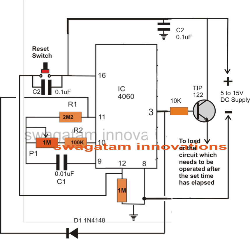
Referring to the shown simple industrial adjustable timer circuit, we can see the IC being the central main component of the whole design.
When power is applied or switched ON, C2 momentarily pulses pin#12 of the IC and resets the timing so that the internal oscillator begins counting from zero, moreover the IC can be reset at any moment during the counting period by pressing the given reset switch.
While the IC counts, the output which is being used (pin#3 here) is held at a low logic level or a zero voltage, which keeps the TIP122 switched OFF
Now as per the setting or selection of R2, P1 and C1, as soon as the set timing elapses, pin#3 goes high, switching ON the transistor and allowing the power to pass to the connected circuit, which now activates.
The feedback diode from pin#3 to pin#11 instantly locks the internal oscillator and latches the circuit so that the circuit freezes in that position until the reset switch is pressed for initiating a new cycle.
Circuit Diagram
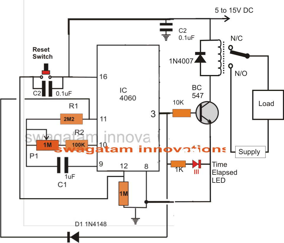
For heavier loads, the above circuit may be upgraded with a relay for identical results but with much higher load current handling capabilities.
Feedback from Mr. Vasilis:

Hello swagatam!
TESTED & WORKING, really happy with the outcome, i used the 2nd circuit with the relay as i didn't have that specific transistor, that would be my last request for you, i hope i wasn't that much of a pain, again really thankful for all the help and effort, god bless you!!
Regards
Vasilis K.


Questions & Answers
Hi
I assembled the circuit with relayoutput,its working for my application ,thanks for ur help,wish u all the best
Sounds great, glad it worked for you!
what is the circuit diagram for cyclic timer switch with adjustable on timing and off timing using potentio meter .
you can try this concept:
https://www.homemade-circuits.com/how-to-make-simple-programmable-timer/
Engr.Swag. you have not answered my question, hope all is well. I need to make a RF switching circuit..or any wireless circuit
Sunshine, which question are you reffering to? there are plenty of wireless circuits in this blog, please use the search box on top and type “wireless”
good day sir….thanks for helping, but engineer Swagatam how will someone show you appreciation? perhaps by giving you gift or any thing..please I need a circuit that will turn ON a relay by 6pm and turn OFF the relay by 6am please help
Thanks sunshine, No problem, I am happy to help without any gifts!
For a 12 hour accurate timer circuit you can perhaps try the following design:
https://www.homemade-circuits.com/how-to-make-long-duration-timer-circuit/
Hi Swagatam,
I have simulated your design plan on proteus, but it does not run.
Can you see if I have simulated properly?
https://imgur.com/n4Ub9Yx
Hi Tanaka, I have tested this circuit practically, for me it worked perfectly. By the way I don’t use simulators, instead I use my knowledge and practical verification for confirming a circuit. Sometimes circuits don’t work initially due to some minor mistake, which we have to troubleshoot with little effort to make them work…
Thanks, i Will try again.
Hello sir Swagatam,
I have connected the circuit as shown in the post with the indicator LED for testing but rather than staying off, the LED keeps blinking before staying on and then resumes blinking again, and then stay on. The process continues indefinitely. What could be the problem sir?
Hello Godson, that shouldn’t happen, because initially the red LED must stay OFF, and as soon as pin#3 goes high after the elapsed period the positive from this pin should latch pin#11 stopping the counting and causing the LED to become solid (pin#3 latched at permanent high).
you can try changing the pin#12 0.1uF cap with a higher value capacitor and see if it helps…also while testing power the circuit from a good 12V DC power supply.
Thank you very much for this post sir. I have been looking for it for some time now. I want to design mine in such a way that I won’t be needing the reset button. I want it to work in such a way that anytime power is applied to it, it activates the Relay for 3hours and then deactivate the relay after three hours until the power source is removed. And when the power source is applied again, the process repeats itself. Here are my questions,
1. In the comment, you said that in order to keep the relay activated during the timing period, the BC547 should be replaced with BC557 and that the emitter should be connected to the positive supply and relay-diode assembly should be connected between the collector of BC557 and GND. Please I need you to confirm that sir.
2. What value of P1 and C1 should I used in order to achieve 3hours of timing? If there is a formula for it, kindly help me with it.
Thank you for all your efforts sir.
Hi Godson, yes that’ correct, use PNP to initiate the relay with power switch ON, the push button is for resetting the timer to zero, it is not required to start the timing, the timer will automatically start as soon as power is switched ON. the reset button can be used to reset the timing to zero anytime.
use any small arbitrary value for C1, note the timing delay for this C1 practically and then divide 3 hours with this delay value.
make sure to convert 3 hours to seconds if the delay value was in seconds.
the answer will be your new C1
Thank you very much for the response sir. I’ll do as you said. In the case of using a PNP transistor, how will the “time elapsed LED” be connected?
connect the LED through a 1K resistor from positive to the pin of the IC associated with the BC557 base
hi swagatam,
is possible obtain a opposte one-shot timer, in other words, when i press the button the load is swicth on for a preset time, elapsed this time, the load switch off and the timer remain in wait for next push.
thank you so much
Hi andrea,
you can achieve it through the first two circuit shown in the following article
https://www.homemade-circuits.com/2012/05/simple-delay-timer-circuits-explained.html
or this
https://www.homemade-circuits.com/2014/11/long-duration-timer-circuit-using.html
or you can also use a IC555 monostable circuit design
Thank u. waiting for the circuit…
you are corect june, in order to get an opposite response, you can try replacing the BC547 with a BC557 and connect its emitter to the positive supply while the relay/diode assembly across the collector/ground of the circuit, this will invert the response of the relay as per your preference
You can use 2 NPN transistors instead of one PNP transistor.
yes that’s possible!
Hi June,
you can achieve up to more than 10 hours of delay with reasonable accuracy with this IC.
P1 and C1 are the two components which directly determine the delay durations, increasing their values will increase the delay length and vice versa. the results will be very linear so it's just a matter of some trial and error until you are able to calibrate the P1 knob dial with the related delay magnitudes (numbers)
gud day can you please post an effective PWM for my HHO. 12v, 60 A.
thanks a lot in advance
you can try the one given in the following link, the motor points may be used as the supply for the electrodes
https://www.homemade-circuits.com/2012/05/make-this-pwm-based-dc-motor-speed.html
Sir.. Can you please design for me a circuit that counts down from 30 seconds to 0,that has a reset button which brings back the timer to 30. And also a pause button,this circuit will serve as a 30 second shot clock for amateur basketball. This is what I need for my school project.
Thank you sir in advance.
Hoping for your help.
Hi Jason, I'll try to do it soon.
sir i already emailed you the diagram.
Helo lwn2012
You will have to show me the diagram that you have constructed only then i would be able to provide an appropriate suggestion.