• Skip to main content
  • Skip to primary sidebar

Homemade Circuit Projects

Need circuit help? Post them in the comments! I've answered over 50,000!

Blog | Categories | About | Contact | Calculators-online
You are here: Home / Arduino Projects / Arduino Mains Failure Battery Backup Circuit

Arduino Mains Failure Battery Backup Circuit

Last Updated on December 5, 2024 by Swagatam 6 Comments

In this article I have explained a simple mains failure backup circuit for providing Arduino boards an uninterruptible supply during such situations. The idea was requested by Mr. Fredrik.

Technical Specifications

This blog gave me a lot of interesting information. Especially the power supply circuit with battery backup part.

The reason for this is that I am working on a Arduino based system for monitoring and controlling heating cables at my summer place.

This system will eventually be gsm controlled so I quickly can get an update on for example the temperature in the bathroom.

The part that I am stuck on is that I would like to have the Arduino to have a battery backup of some sort so it can still monitor the temperature around vulnerable waterpipes, and possible notify me if mains power goes out. I'm thinking of using a car battery so it can last for ages if power goes out.

What changes will I have to make to the "Power Supply Circuit with Emergency Backup" circuit to make it work with a 12V car battery and still have it trickle charge slowly?

Thank you in advance for any advice.

Sincerely
- Fredrik

Circuit Diagram

Arduino Mains Failure Battery Backup Circuit Diagram

The Design

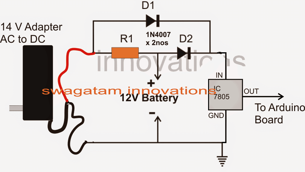
The simplest way to implement the proposed application is by using two diodes as shown in the above diagram.

The design shows two diodes with their cathodes connected together and anodes terminated to a 14 V source and anodes to the positive of a 12 V battery source respectively.

The common cathodes of the diodes are further connected to a IC 7805 IC whose output is finally applied to the Arduino board.

When mains is present the 14 V supply ensures s constant trickle charge supply to the attached battery via R1 and also feeds the Arduino borad through D1 and the 7805 IC.

In this situation D1 cathode experiences a much higher potential than the cathode of  D2 due a relatively lower battery potential at D2 cathode.

The above situation keeps D2 reverse biased allowing the battery charge to stay blocked and pass only the adapter voltage to the Arduino board.

But as soon as the mains supply fails, D1 instantly stops conducting and enables D2 to get forward biased so that now the battery instantly takes over and begins supplying the Arduino via the 7805 IC.

You'll also like:

  • 1.  Making a Single Channel Oscilloscope using Arduino
  • 2.  Making an Automatic Stopwatch for Runners, Athletes and Sportpersons
  • 3.  How to Send and Receive SMS Using GSM Modem
  • 4.  Car Reverse Parking Sensor Circuit with Alarm
  • 5.  How to Make Arduino on Breadboard – Step by Step Instructions
  • 6.  Make this Simple Weather Station Project for Homes and Offices

About Swagatam

I am an electronics engineer with over 15 years of hands-on experience. I am passionate about inventing, designing electronic circuits and PCBs, and helping hobbyists bring their projects to life. That is why I founded homemade-circuits.com, a website where I share innovative circuit ideas and tutorials. Have a circuit related question? Leave a comment.... I guarantee a reply!

Previous Post: « Customizing Car Side Marker Lights to Flashing Side Markers
Next Post: 32V, 3 Amp LED Driver SMPS Circuit »

Reader Interactions

Comments

  1. Kesava Raj says

    December 29, 2016 at 7:55 am

    Another 1 doubt sir….

    This circuit i'm using for CD4017

    D2 output shall i connect resistor…..
    To limit the current…bcs i'm using 4v 1A ….sometimes in my area continuously power cut may be 7 hrs….
    So when i use resistor..The backup time will be high…

    How much current will required for cd4017

    Reply
    • Swagatam says

      December 29, 2016 at 4:36 pm

      even without a resistor the IC will not consume more than 5mA….but you can use a resistor in the backup mode to reduce this 5mA to a lower value may be 2mA to just keep the IC "alive" during that period

      Reply
  2. Kesava Raj says

    December 29, 2016 at 1:47 am

    V/I

    Input 5v
    Current 800ma…

    5/800ma =6.25 ohms sir

    Wattage of resistor is 1.28 watts…

    Is it correct sir

    Reply
  3. Kesava Raj says

    December 29, 2016 at 1:41 am

    Thank u sir

    Reply
  4. Kesava Raj says

    December 28, 2016 at 12:17 pm

    Hai sir…
    I'm using this circuit without 7805.
    Battery voltage is 4v 1A lead acid batteries….

    Backup power supply for IC…
    Kindly tell the resistor value for charging the battery….
    Daily night 10 hrs i will use this circuit in the between of 10hrs the power supply failure.in that it will work….
    So i need slow charging method…

    Main input dc voltage i'm using 7805 output voltage and 1ampere diode….
    …
    Resistor value and watts i need sir..

    Reply
    • Swagatam says

      December 28, 2016 at 3:09 pm

      Hi kesava, you can use ohms law for this

      R = V/I…

      V is the input supply voltage, I is the charging voltage which is 100mA or 0.1Amp in your case

      wattage = I^2 x R

      Reply

Need Help? Please Leave a Comment! We value your input—Kindly keep it relevant to the above topic! Cancel reply

Your email address will not be published. Required fields are marked *

Primary Sidebar

Subscribe to New Circuit Ideas

Categories

  • Arduino Projects (87)
  • Audio and Amplifier Projects (132)
  • Automation Projects (17)
  • Automobile Electronics (101)
  • Battery Charger Circuits (82)
  • Datasheets and Components (102)
  • Electronics Theory (143)
  • Free Energy (37)
  • Games and Sports Projects (11)
  • Grid and 3-Phase (19)
  • Health related Projects (25)
  • Home Electrical Circuits (12)
  • Indicator Circuits (14)
  • Inverter Circuits (87)
  • Lamps and Lights (142)
  • Meters and Testers (69)
  • Mini Projects (46)
  • Motor Controller (64)
  • Oscillator Circuits (27)
  • Pets and Pests (15)
  • Power Supply Circuits (108)
  • Remote Control Circuits (50)
  • Security and Alarm (64)
  • Sensors and Detectors (100)
  • Solar Controller Circuits (59)
  • Temperature Controllers (42)
  • Timer and Delay Relay (49)
  • Transmitter Circuits (29)
  • Voltage Control and Protection (37)
  • Water Controller (36)

Calculators

  • Battery Back up Time Calculator
  • Capacitance Reactance Calculator
  • IC 555 Astable Calculator
  • IC 555 Monostable Calculator
  • Inductance Calculator
  • LC Resonance Calculator
  • LM317, LM338, LM396 Calculator
  • Ohm’s Law Calculator
  • Phase Angle Phase Shift Calculator
  • Power Factor (PF) Calculator
  • Reactance Calculator
  • Transistor Astable Calculator
  • Transistor base Resistor Calculator
  • Voltage Divider Calculator
  • Wire Current Calculator
  • Zener Diode Calculator
  • Filter Capacitor Calculator
  • Buck Converter Calculator
  • Boost Converter Calculator
  • Solar Panel, Inverter, Battery Calculator
  • Wire Current Calculator
  • SMPS Transformer Calculator
  • IC SG3525, SG3524 Calculator
  • Inverter LC Filter Calculator

People Also Search

555 Circuits | 741 Circuits | LM324 Circuits | LM338 Circuits | 4017 Circuits | Ultrasonic Projects | SMPS Projects | Christmas Projects | MOSFETs | Radio Circuits | Laser Circuits | PIR Projects |

Recent Comments

  • Swagatam on Simple Delay Timer Circuits Explained
  • Swagatam on The Role of Inductor Coil in SMPS
  • Swagatam on 7 Modified Sine Wave Inverter Circuits Explored – 100W to 3kVA
  • Swagatam on 7 Modified Sine Wave Inverter Circuits Explored – 100W to 3kVA
  • Victor on 7 Modified Sine Wave Inverter Circuits Explored – 100W to 3kVA

Company

  • Privacy Policy
  • Cookie Policy
  • About Me
  • Contact
  • Disclaimer
  • Copyright
  • Videos
  • Sitemap

Social Profiles

  • Twitter
  • YouTube
  • Instagram
  • Pinterest
  • My Facebook-Page
  • Quora
  • Stack Exchange
  • Linkedin
  • © 2025 · Swagatam Innovations