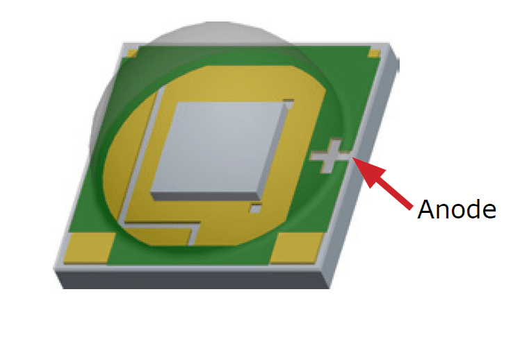
The XLamp XM-LED can be considered as the highest performing, single die solid state LED module which is able to produce lights at ultra bright intensities. I have explained it's datasheet, specifications.
High Illumination Efficacy
Due to it's ultra bright and high efficiency values, the Xlamp becomes highly suitable for applications such as in automotive headlamps, stadium flood lights, for home lighting, street lighting, practically anywhere which requires high illumination at minimum space and consumption.
To be precise an Xlamp is able to generate 1000 lumen with 100 lumen per watt efficacy.
The main features which makes this breakthrough device exceptionally desirable for lighting applications may be studied with the following data:
Main Electrical Specifications
- Operating current: 3000 mA or 3 Amps
- Operating Voltage: 3.3V
- Low thermal resistance: 2.5 °C/W
- Maximum junction temperature: 150 °C
- Viewing angle: 125°
- Available in cool white, 80‑CRIminimum neutral white and 80‑CRI, 85‑CRI and 90‑CRI warm white
- ANSI‑compatible chromaticity bins
- Infinite Store life at ≤ 30 ºC/85% RH
- Re flow solderable - JEDEC J‑STD‑020C
- Electrically neutral thermal path
- RoHS- and REACh‑compliant
- UL-recognized component (E349212)
How to Drive a Cree Xlamp XM-LED
Since the the performance and life of the Cree Xlamp is inversely proportional to its junction temperature, a high quality current controlled driver becomes a must for operating these ultra bright LEDs. I have explained a few of the application circuits for safely driving the proposed LED devices.
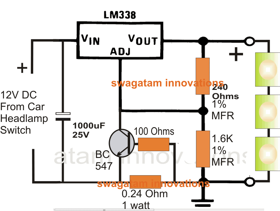
Applying In Automotive Headlights.
When used for automotive headlamp applications, the following circuit may be employed:
For Home Lighting
The same circuit may be used for home lighting applications, the design is given below:
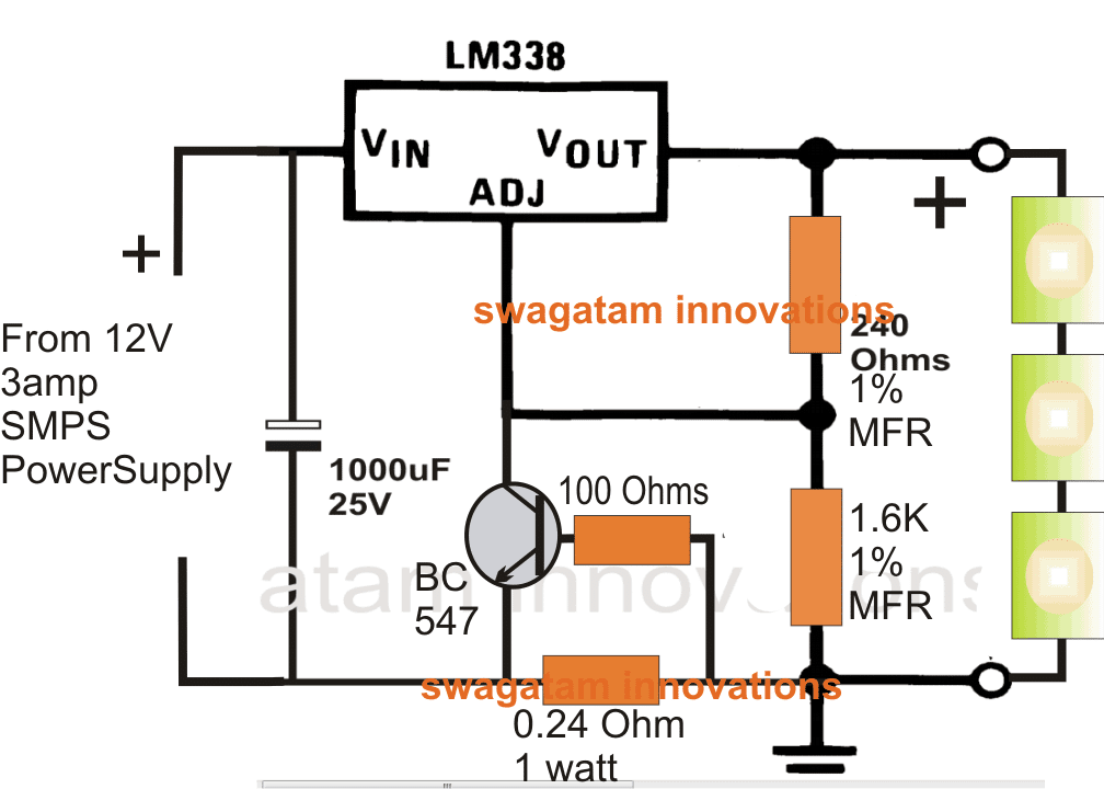
For all applications, the LEDs must be mounted on suitable heatsinks for getting optimal performance.
For more info on this, you may refer to the original datasheet


Questions & Answers
sir, i want to use a single 5w cree XML led for automotive …
what will be circuit for that
Abdullah,
you can attach any desired LED through an appropriate current limiter stage as explained in the following article:
https://www.homemade-circuits.com/universal-high-watt-led-current-limiter/
Hi, is this circuit can be used for automotive headlight purpose where input volt with be 12~15v. Also can we able to connect Cree XML T6 10w led X 3 Nos? and what will be the output Amp.
output amp will be 10/12 = 0.83 amps
yes it can be used for automotive headlight purpose.
3 x 10 watt can be used with the above shown circuits, make sure to calculate the 0.24 resistor accordingly
The 1% resistors can be 1/4 watt types while the 0.24 ohm resistor is 1 watt, wire-wound type.
thanyou very mach
1amp, 500v thermistor will do the job..
you can use 105/400v as the capacitor but include a thermister at the input to prevent LED damage and blackening.
which rate of thermistor use for this circuit.474 use after 8 mm led light not enough and it take 19mA when i use 105 it take 39mA .also 56 ohm resister i will use metal oxide type.why led middle came a black point? p[lease explain me to this problem
use 474/400v capacitor in place of 105, and connect a thermistor at the input. The thermistor explanation can be found here:
https://www.homemade-circuits.com/2013/02/using-ntc-resistor-as-surge-suppressor.html
sir i will made 230v led bulb 8mm 0.5w 55 led for each circuit .when i make this bulb starting give good bright light ,after 2 or 3 month it loss 40 percent light and led chip middle have black point.why loss light of this led please inform to me what the wrong of this circuit
i use following parts of this circuit
105 capacitor mylor
56 ohm 1w resister
22uf capacitor and 890k,560 k resister 0,25w
4 pcs diode