• Skip to main content
  • Skip to primary sidebar

Homemade Circuit Projects

Get free circuit help 24/7

New Projects | Privacy Policy | About us | Contact | Disclaimer | Copyright | Videos 

You are here: Home / Datasheets / IC 4024 Datasheet, Pinout Working, Application Circuit

IC 4024 Datasheet, Pinout Working, Application Circuit

Last Updated on February 28, 2023 by Swagatam Leave a Comment

IC 4024 is a 7-stage binary ripple counter with a divide-by-two section and a reset input. It is a CMOS integrated circuit and can operate at a wide range of supply voltages.

Here is a datasheet for the IC 4024:

General Description

The IC 4024 is a 14-stage binary ripple counter with a divide-by-two section and a reset input. It is designed for use in digital counting applications and features a wide supply voltage range and low power consumption.

Electrical Characteristics

  • Supply voltage range: 3V to 18V
  • Maximum clock frequency: 20 MHz
  • Input capacitance: 5 pF
  • Power supply current: 5 mA (max)
  • Low output voltage: 0.5V (max)
  • High output voltage: VDD - 0.5V (min)
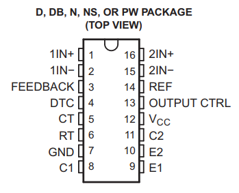
Pin Configuration

The pinout configuration of the IC 4024 can be learned from the following explanation and the pinout diagram.

caution electricity can be dangerous
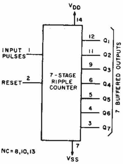
  • Pin 1: Clock Input (CP)
  • Pin 2: Reset Input (MR)
  • Pin 3: Output 1 (Q7)
  • Pin 4: Output 2 (Q6)
  • Pin 5: Output 3 (Q3)
  • Pin 6: Output 4 (Q5)
  • Pin 7: Ground (Vss)
  • Pin 8: Not Connected
  • Pin 9: Output 5 (Q3)
  • Pin 10: Not Connected
  • Pin 11: Output 6 (Q2)
  • Pin 12: Output 7 (Q1)
  • Pin 13: Not Connected
  • Pin 14: Positive Supply VDD

Functional Description

The IC 4024 is a 14-stage binary ripple counter. The counter increments on the rising edge of the clock input (CP). The divide-by-two section produces a half-frequency output on output 6 (Q6). The reset input (MR) resets the counter to zero when it is pulled low.

There are 7 outputs for the IC 4024. The outputs are Q1, Q2, Q3, Q4, Q5, Q6, Q7.

The number beside the Q indicates by what figure it divides the input pulses to produce a divided output.

Let's take the example of pin#3 which is a Q7 output.

Q7 means, it divides the input pulses at pin#1 by 27 = 128.

If, let's assume that the clock frequency at pin#1 is 512 Hz, then this 512 will be divided at the output pin#7 by 128. The result will be 512 / 128 = 4 Hz.

Therefore, if there's a 512 Hz frequency at pin#1 then pin#7 will divided it by 2 to generate a 4 Hz frequency.

The same applies for the other outputs. For example pin#4 which is Q6 will divide by 26 , pin#5 which is Q5 will divide by 25 ans so on.

Applications

The IC 4024 is commonly used in digital counting applications, such as frequency dividers, timers, and clocks.

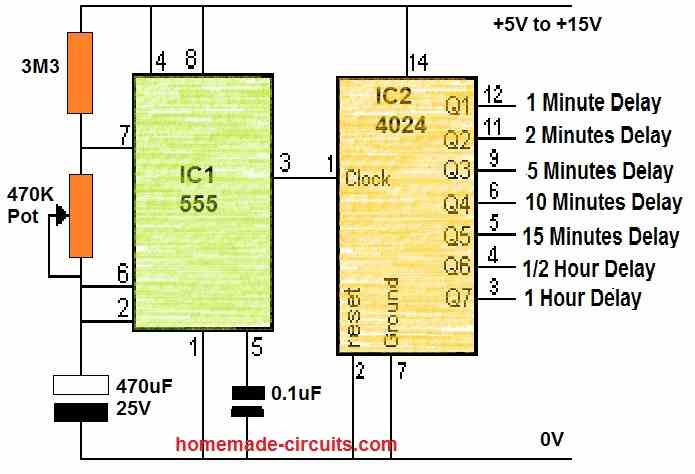
One example application circuit can be seen in the following figure which can used to generate long duration delay timings from a IC 555 oscillator.
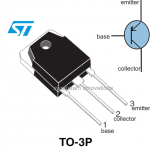
Package Type

The IC 4024 is available in a variety of package types, including DIP (Dual Inline Package) and SOP (Small Outline Package).

Manufacturer

The IC 4024 is manufactured by various semiconductor manufacturers, including Texas Instruments, STMicroelectronics, and NXP Semiconductors.

You'll also like:

  • 1.  IC 4020 Datasheet, Pinout Functioning Explained
  • 2.  EGS002 Datasheet, Circuit Diagram Explained
  • 3.  TIP127 Datasheet [100V, 5 Amp PNP Darlington Transistor]
  • 4.  IC TDA 7560 Datasheet – 4 x 45W QUAD BRIDGE CAR RADIO AMPLIFIER PLUS HSD
  • 5.  IC 4070 Datasheet, Pinout Working, Truth Table, Electrical Characteristics
  • 6.  High Current Triac BTA41/600B – Datasheet, Application Note

About Swagatam

I am an electronic engineer (dipIETE ), hobbyist, inventor, schematic/PCB designer, manufacturer. I am also the founder of the website: https://www.homemade-circuits.com/, where I love sharing my innovative circuit ideas and tutorials.
If you have any circuit related query, you may interact through comments, I'll be most happy to help!

Have Questions? Please Comment below to Solve your Queries! Comments must be Related to the above Topic!!

Subscribe
Notify of
0 Comments
Inline Feedbacks
View all comments

Primary Sidebar

Categories

  • 3-Phase Power (15)
  • 324 IC Circuits (19)
  • 4017 IC Circuits (52)
  • 4060 IC Circuits (26)
  • 555 IC Circuits (99)
  • 741 IC Circuits (20)
  • Arduino Engineering Projects (83)
  • Audio and Amplifier Projects (115)
  • Battery Chargers (83)
  • Car and Motorcycle (95)
  • Datasheets (74)
  • Decorative Lighting (Diwali, Christmas) (33)
  • Electronic Components (101)
  • Electronic Devices and Circuit Theory (36)
  • Electronics Tutorial (120)
  • Fish Aquarium (5)
  • Free Energy (34)
  • Fun Projects (13)
  • GSM Projects (9)
  • Health Related (20)
  • Heater Controllers (29)
  • Home Electrical Circuits (103)
  • How to Articles (20)
  • Incubator Related (6)
  • Industrial Electronics (28)
  • Infrared (IR) (40)
  • Inverter Circuits (98)
  • Laser Projects (12)
  • LED and Light Effect (93)
  • LM317/LM338 (21)
  • LM3915 IC (25)
  • Meters and Testers (66)
  • Mini Projects (149)
  • Motor Controller (67)
  • MPPT (7)
  • Oscillator Circuits (26)
  • PIR (Passive Infrared) (8)
  • Power Electronics (34)
  • Power Supply Circuits (79)
  • Radio Circuits (10)
  • Remote Control (48)
  • Security and Alarm (62)
  • Sensors and Detectors (121)
  • SG3525 IC (5)
  • Simple Circuits (75)
  • SMPS (29)
  • Solar Controllers (61)
  • Timer and Delay Relay (53)
  • TL494 IC (5)
  • Transformerless Power Supply (8)
  • Transmitter Circuits (41)
  • Ultrasonic Projects (16)
  • Water Level Controller (45)

Calculators

  • AWG to Millimeter Converter
  • Battery Back up Time Calculator
  • Capacitance Reactance Calculator
  • IC 555 Astable Calculator
  • IC 555 Monostable Calculator
  • Inductance Calculator
  • LC Resonance Calculator
  • LM317, LM338, LM396 Calculator
  • Ohm’s Law Calculator
  • Phase Angle Phase Shift Calculator
  • Power Factor (PF) Calculator
  • Reactance Calculator
  • Small Signal Transistor(BJT) and Diode Quick Datasheet
  • Transistor Astable Calculator
  • Transistor base Resistor Calculator
  • Voltage Divider Calculator
  • Wire Current Calculator
  • Zener Diode Calculator

© 2023 · Swagatam Innovations

wpDiscuz