In this post I have explained a simple configuration which can be used as a automatic changeover circuit for switching AC grid mains to generator mains, during power failures or outages.
The explained circuit will effectively switch the connected appliances to the generator mains during power failure however it won't be able to switch start the generator automatically, this will need to be done manually, because most generators involve a difficult mechanical actuation procedure.
How it Works
Referring to the given diagram we can see a simple circuit comprising of a TP relay (triple pole relay) as shown below, and a transformerless power supply circuit.

The input of the transformerless power supply circuit is connected to the mains 220V or 120V input.
When mains power is present, the connected relay activates with this power and switches ON the load or the appliances via its N/O contacts.
Conversely when mains power fails, the relay deactivates and connects with the N/C contacts which may be wired up with the generator mains.
Now as soon as the generator is pulled started, the mains finds its way through the connected N/O contacts of the relay to the appliances.
The third set of contacts is used for enabling and disabling of the CDI unit of the generator so that when mains is restored, the generator is automatically halted.
Simple yet effective.....
Circuit Diagram
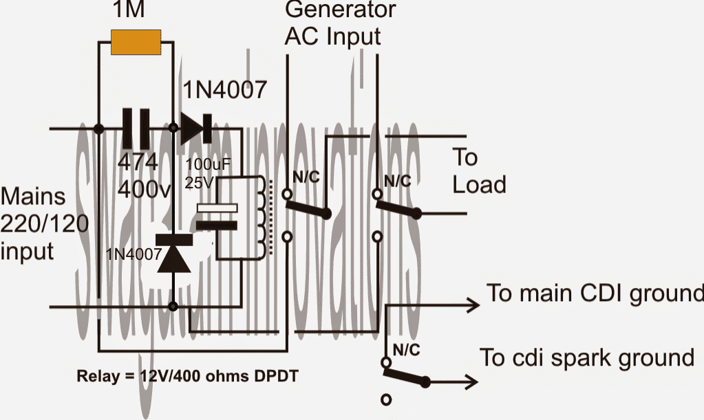
Analyzing the Part Value Calculations
Voltage Divider Across the Relay (Using 474 Capacitor)
The 474 capacitor (0.47 µF, 400 V) acts as a current limiting element for the relay coil when connected to the AC mains (220 V or 120 V). The current through the capacitor can be calculated using the reactance of the capacitor:
Formula for Capacitive Reactance:
Xc = 1 / (2 * π * f * C)
Where:
- Xc = Capacitive reactance in ohms
- f = Frequency of AC mains (typically 50 Hz or 60 Hz)
- C = Capacitance in farads (0.47 µF = 0.47 * 10⁻⁶ F)
For 50 Hz mains: Xc = 1 / (2 * π * 50 * 0.47 * 10⁻⁶)
Xc ≈ 6,778 ohms
Current Through the Relay:
The current is determined by Ohm’s Law:
I = V / Xc
For 220 V AC mains:
I = 220 / 6,778 ≈ 0.0324 A ≈ 32.4 mA
For 120 V AC mains:
I = 120 / 6,778 ≈ 0.0177 A ≈ 17.7 mA
This current must be sufficient to activate the relay. Check the relays required current (based on its 12 V 400-ohm coil):
Relay Voltage and Power
The relay coil operates on 12 V DC. The current through the coil is:
Irelay = V / R
Where:
- V = Voltage across the relay coil (12 V)
- R = Relay coil resistance (400 ohms)
- Irelay = 12 / 400 = 0.03 A = 30 mA
This means that the capacitor-limited current (calculated above) has to be greater than or equal to the relay's required operating current of 30 mA for 220 V mains.
Diode Rectification
The diodes (1N4007) rectify the AC voltage into pulsating DC for the relay coil. The peak DC voltage after rectification is:
Formula for Peak Voltage:
Vpeak = Vrms × √2
For 220 V AC mains:
Vpeak = 220 * √2 ≈ 311 V
For 120 V AC mains:
Vpeak = 120 * √2 ≈ 170 V
However the relay sees only the voltage dropped across the capacitor and rectified output which limits the current to safe levels.
Filtering Using 100 µF Capacitor
The 100 µF capacitor smooths the rectified pulsating DC into a steady voltage for the relay.
The ripple voltage can be estimated using:
Ripple Voltage Formula:
Vripple = I / (f * C)
Where:
- I = Current through the capacitor (relay current, ≈ 30 mA)
- f = Frequency of rectified signal (100 Hz for full-wave rectification in 50 Hz mains)
- C = Capacitance in farads (100 µF = 100 * 10⁻⁶ F)
Vripple = 0.03 / (100 * 100 * 10⁻⁶)
Vripple ≈ 3 V
3 Phase Grid to Generator Changeover Circuit
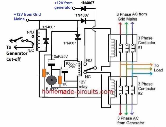
The following diagram shows how a 3 phase grid to generator changeover can be implemented using a couple of 3 phase contactors.
How the Circuit Works
Let's assume mains AC is not available, and generator is switched ON by the left side relay.
In this situation the center relay will be deactivated, and its pole will be connected with its N/C contact, so that the +12V DC from the generator passes through the N/C contact and actuates the bottom/right 3 phase generator contactor.
The top/right grid mains contactor remains switched OFF due to the absence of a +12V DC.
Therefore, the generator AC flows through this bottom/right contactor and operates the connected appliances or load.
Now, suppose the mains grid AC restores.
The left side relay activates and turns OFF the generator. Also, simultaneously the center relay switches ON through the +12V from the grid mains.
The center relay pole now shifts from N/C to N/O, so that the +12V from the mains grid AC passes through the N/O contacts and actuates the top/right contactor. The bottom/right generator contactor is simultaneously switched OFF.
With the top/right contactor switched ON, the grid AC now becomes available to the load.
Again, if the mains AC fails, the left side relay deactivates, switching ON the generator procedures, the center relay connects with its N/C contacts, turning on the generator 3 phase contactors and turning OFF the grid contactors.
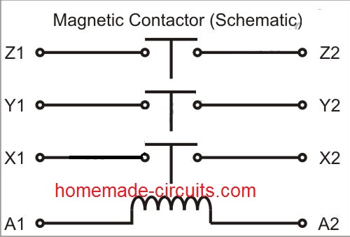
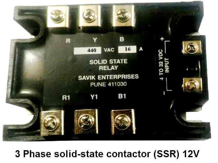
If you are unable to get the above 12V electromechanical relay/contactor, you can go for a 3 phase SSR contactor instead, as shown below.


Questions & Answers
Hello good afternoon Mr. Swagatam, my name is Carlos and I am a faithful follower of the website, in this opportunity I would like to ask you if you have a circuit. I need to energize a relay for 2 to 3 seconds.
I mean… When voltage is applied the relay is maintained 2 to 3 seconds and is released …. Even if the power supply is still present. Thank you very much.
Thank you Carlos,
You can try the following design for your specific application:
https://www.homemade-circuits.com/wp-content/uploads/2021/07/transistor-monostable-compressed-compressed.jpg
You can replace the load with your relay. Make sure to connect a freewheeling diode across the relay coil.
You can adjust the values of the 1k resistors and the 1uF capacitor for adjusting the relay delay off time.
Hi Swagath,
I have an inverter with SCR as the switching element (Luminous iCruze 3000). I would like to add a relay before the input of inverter so that the relay prevents any backfeeding of supply to mains in the event of SCR failure. I opt for this circuit and prefer to to use a transformer to power up the relay mentioned in your circuit instead of capacitor. Any modifications required?
Hi Sanoj,
That appears to be a good idea.
You can surely replace the entire capacitive power supply with a transformer based power supply with a bridge rectifier and a filter capacitor. Just make sure the DC output from the transformer power supply matches the relay coil voltage rating, up to +20% is quite acceptable.
You can connect the DC output from the filter capacitor directly with the relay coil.
Also, please replace the 100uF/25V capacitor across the relay coil with a freewheeling diode 1N4007.
I built this one,, change over was exactly what I was looking for. The one problem I ran into was the relay was 120 ohms. So I did away with I 1 Meg resistor and put a transformer for the 12 volts. Thanks for your massive web site of great knowledge.
Thank you Art, glad the circuit worked for you.
All the best to you.
Perfect thanks
I am looking at your grid tie circuit. I have 120 volt coming from the main and I have a 120 volt inverter. Up to now I unplug from the main and plug into the inverter, there has to be a way so I done have to unplug anything just flip a switch from one to another and if course back. I see one if your diagrams above but not sure. I keep seeing circuits but they have added the inverter circuit. I don’t need another inverter. Just a change over from one to another. Thanks
I think you can simply do it with a DPDT switch, as shown below:
https://www.homemade-circuits.com/wp-content/uploads/2024/06/grid-to-dpdt-changeover.jpg
Good day sir, please I need a circuit that will automatically switch on a generator that has manual start facility when the mains power is off. That is just what I want
Moses, I think you should use a readymade control box which has automatic start and stop facility, building a circuit can be complex because generators cannot be started just by a push of a button
Hi, thanks for your informative page, just what I was looking for. In the first diagram you have a capacitor “474” – 474 what?
Thanks, Dan
Hi, the capacitor 474 is equivalent to a 0.47uF/400C PPC capacitor
Thanks!
I have a suggestion. How difficult would it be to add some sort of timer to the CDI switch output so the generator can run with the mains on, then be switched to when the mains goes off, and then be killed when the mains comes on again? This would allow you to test the switchover from mains to generator.
For delaying the CDI switch in the first diagram, you will have to isolate the CDI switch with a separate relay which must be connected with the main relay. The main relay now becomes DPDT relay and the CDI relay becomes SPDT relay. The timer could be added with this SPDT relay
Yes, the wiring is very simple. But my fear is if generator is switched on already and suddenly, mains supply becomes available, if your are using AH3-3 delay relay off timer, the pole of the center relay clicks the NO to power mains contactor (while generator runs for few seconds or minutes depending on the set timing to switch off), power supply from generator will still find its way to the mains circuitry via pole to the NO contacts of the center relay which can cause a short circuit.
The operation of the center relay can never keep the two contactors ON at the same instant. When it moves to N/O, the N/C side contactor releases, and vice versa.
Hi Swagatam, how are you doing? Having gone through the circuit thoroughly, I now realized that I have been mistaken all along. Without void of doubt, the diagram is very much ok. I didn’t do much due diligence on it that resulted to my conclusion. I’m sorry that our last conversation didn’t go well.
Regards.
Hi Olakunle, I am good, thank you! Not a problem at all! It is just a part of the learning process for all of us! I am glad the confusion is over now! Please keep up the good work!
Having gone through the schematic diagram diligently, I ran a simulation on Proteus CAD. These are my observations
1. Connecting different power supply on the pole of center relay is dangerous should the relay fails.
2. Mains power supply takes priority over generator that’s why on the center relay, NO contact is for mains, NC- generator and pole, load. It’s best to separate these contacts accordingly.
3. If you are using a delay-relay timer, the circuit can poise an hazard in that when generator is running and mains supply is available, generator will still be running. After the time interval of the timer lapses, generator stops working. You can see why generator and mains shouldn’t be connected to the pole.
Resolution
1. Disconnect generator +12V power supply from pole of center relay and connect pole back to +12V mains power supply (as in your previous schematic diagram before changing it to the present one). Now, disconnect the upper generator contactor coil from NC of center relay and connect it to generator +12V power supply. Since the lower contactor coil of both generator and mains are connected to ground, that forms the interlock. This arrangement is situable if you want to use a delay-relay timer. That coil will be connected to a timer. The moment generator starts, it will be delay the supply like 20secs (depending on the setting) before powering the load. By that time, the generator would have attained its maximum speed.
2. You can still maintain your previous schematic diagram which is ok.
The wring is very simple it can be simulated in mind to know the results, without any software.
The pole of the relay is connected to 12V DC from the generator and the mains grid AC, and the N/O N/C contacts are connected to the coils of the contactor relay.
There’s no AC present anywhere on the pole of the center relay.
The center relay only controls the contactor coils.
If the center relay fails, at the most there will be no AC to the load….and that’s all…there is absolutely no chance of any hazardous situation.
The two contactors on the extreme right can NEVER EVER operate at the same time, and therefore there’s absolutely no chance of any electrical hazard.
Your diagram, among others is too simple for me not to understand it. Using Proteus has nothing to do with my logic abilities. I use it to simulate all my designs and to also check mate possible features or amendments where necessary. If you say what you did is ok, then no problem. We are all entitled to our opinions.
Besides, what do you mean by strong 12VDC from generator and mains? I asked you a simple question that where lies the interlock in your connections. But you seem confused not to understand but instead you change the circuit diagram of which the previous diagram is much more better that the present one.
The center relay ensures the interlock feature.
The center relay ensures that the two contactors can never operate at the same time.
I think I have already explained this many times, it’s no point discussing the same thing again and again.
The previous diagram did not have a 12V from the generator, then how could the generator side contactor operate when the center relay contacts connect to the N/C points? To correct this, I added the +12V from the generator.
If you have used some external delay/relay with my circuit then that’s your problem. I cannot suggest about it since I have not seen the schematic.
Although not required, a delay feature can be added with the center relay and should be discretely built without depending on external circuits. In fact I have already provided the delay feature by adding a 1000uF capacitor with the center relay coil.
Proteus is a good software, but it is good only as long as the user has good knowledge of electronics, otherwise the results can be erroneous.
The bold 12V indicates only a DC is involved to operate the relays, and two DCs create nothing hazardous with the center relay….
The second diagram is fail-safe, failproof, hazard proof, under all circumstances.
I have not used any delay relay timer for the contactors, that is your version, and might require a completely different circuit.
Thank you for that response. Now, how does the relay gets energized (i.e. to supply power to the first contactor) when there is mains supply considering the fact that the pole or (com) of that relay is connected to the generator 12VDC supply?
When mains supply is present the generator will be switched OFF, and the center 12V relay pole will connect with its N/O contacts, and that will allow the Grid mains contactor to energize. The wiring is very simple, please check the 12V path across the relay contacts and the contactor coils….
I take it that the control cct is fed from a mains phase ?
yes that’s correct!
I have noticed that all changeover (generator-grid) circuits feature two contactors, one for the generator and one for the grid. Why can’t one contactor, with an array of NO and NC contacts do the job? Possibly extra safety? What can go wrong with a single contactor?
Thanks in advance.
Can you show me the contactor diagram link? I’ll try to figure it out.
The schematic is previously on this page (near the top).
Accommodating all the mechanism inside one unit can make the system congested and cluttered which may not be recommended for high power systems.