The post provides interesting information regarding the making of a 1.5V to 12V converter circuit using a couple of transistors and an inexpensive coil. The idea was requested by Mr. Keith.
The Circuit Request
I found your blog and have searched for an answer to my question but I'm just not finding it....
What I want to do is use 4 x 3v "2032" coin batteries connected in parallel to get long lasting life out of them. Then using a "Joule Thief" circuit up the out-put voltage to 12.5v - 14v to drive a set (3) of color changing LED's or a 12v LED light bulb found on ebay (here is the link to the bulb...
Now here is the other part of my problem, I don't want to use a wire wound transformer !!!! I would like the Joule Thief circuit to use transistors or some other easy to get materials because at the end of all of this I am going to encased the whole project in clear resin..
Any help would be great... A wiring schematic with parts labeled would help also.
Thanks,
Keith
Solving the Circuit Request
Hello,
Thanks for contacting me!
I am afraid without a coil it wouldn't be feasible to create a joule thief effect, because the coil is the maincomponent which enables complete extraction of energy from a depleting source.
Regards.
Feedaback from Keith
I thought that is what you would say. Is there a way to design it with a ferrite core coil that is available "off the shelf" i.e. Radio Shack or Digi-Key, so I don't have to make my own.
And could you design it? Also would there be any issues with encasing this project in liquid resin? The resin will cure within 24 hours and I am just wondering is there any issue with the coil not being able to get "fresh air" and getting too hot and eventually burning up. By the way the on/off switch is a mercury switch.
Would any of these work? I know that my power requirements maybe more or less than 330uh, I just search for that size because I remember seeing that being used by this project:
https://www.instructables(dot)com/id/Joule-Thief-no-IC-and-no-Transformer/
If none of this works can you please send me a wiring schematic with labels for parts that does include a wire coil and I will just build it that way.
Thanks again,
Keith
Analyzing the Circuit Idea
The 1.5V to 12V converter circuit provided in the above "instructables" link would possibly do the job. The second digikey link coil is the one which exactly suits the design, so you can try it out.
Epoxy resin sealing would be fine, it won't do any harm to the inductor.
Regards.
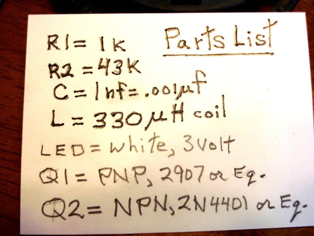
Circuit Diagram
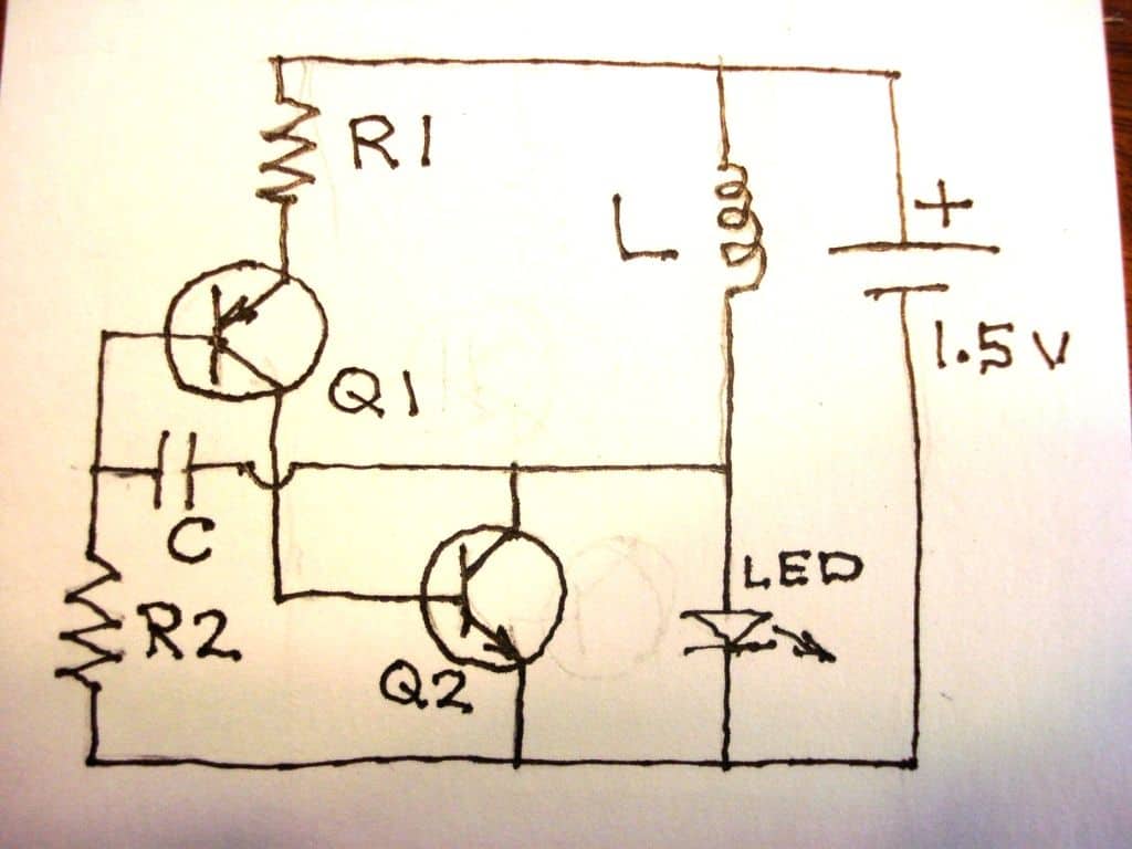
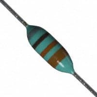
Inductor 300uH or similar (Picture)
Questions & Answers
Hello
Is it possible to setup that out to higher values please
If so kindly show me a design
If you want to increase the output voltage level, you can try a higher value inductor, for example a 500 uH or a 800 uH etc.
Sir swagatam, most times, we do not have the wire you are using. We only have what looks like it. Specifying the unit in microhenry’s(uh) would help us to calculate the windings with our own wire. Thank you!
It is mentioned in uH
Can I use this circuit for 3.7v to 5v 1A?
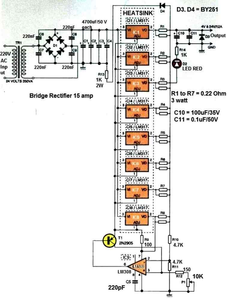
1 amp may not be possible, you should use specialized IC such as this:
hi sir… what i need is 12vdc step down to 1.5v…3v..6v…9v circuit can you help me please… thank you so much in advance…
Hi Dax, you can use a n LM317 base variable regulator circuit for that.
1.5vto220vACinverter
very informative article sir
Thanks!!
Have you tried this circuit sir?…tnx
No…it was posted in instructables, I took it from there.
Please, I'm just looking for a circuit that could step-up 1.5V (AA cell) to 6V, in order to replace old battery used in HP calculators and their weird chargers or wall adapters. Could your circuit output 6V at 200mA from one 1.5V AA battery?
Agree 🙂
Hi Abu-Hafss, in any power supply circuit the load must be selected such that it matches the power supply output or conversely it could be the power supply whose output should be matched with the load parameters.
here too if suppose the output is 50V, 1 mA,the load must be also rated with similar specs to operate correctly, in contrast if we connect say a 3V 1 amp load then that won't work and the converter would fail to operate, therefore the circuit must be dimensioned appropriately to match the load parameters and vice versa.
Hi Swagatam
Yes, you are right without load the output can reach a few hundred volts but practically that high voltage cannot be harvested.
Hi Abu-Hafss, the voltage is dependent on the number of turns to a great extent, so please try tweaking the turns only and check the output without connecting any load, you will surely see the voltage proportionately increasing or decreasing accordingly.
Hi Swagatam
This circuit is just another variant of Joule Thief, the maximum output is just above 1.9V enough to light up an LED. I have tried to tweak with different component values but no change, only increase/decrease current output.
Can your 1.5V cell output 200mA?
the answer is no, so the above circuit also will not produce above 50mA, but it can produce 6V.
You can also try a joule thief circuit for the same
can i use 10 led by two in series
you can try
it could reach upto 20V
Sorry for my writing is not clear that make you confuse. I mean to convert from li-ion battery 3.7v to 12v sir.
where can i get 12v i only get 3v from 3.7v battery
Hi Seoke,
for 300ma you would have to make the following changes in the circuit.
For T2 use 2N2222,
Use a hand wound inductor of the same value using a thicker wire, may be a 0.5mm or so.
Hi! sir. Can i use this circuit to convert from 3.7v to 12v to supply a pc fan (12v, 300ma)? If can, which components i should replace?
Hi Seok,
Yes you can try it, it should work if the PC current is within few tens of mA
Please sir, can this circuit power power the ic NE555 very well? And can it last for a long time with the ic if i connect 4 of the 1.5v cells in parallel since they will be producing 6amp?
4 nos 1.5v cells will not produce 6amps, they will become rated at 6AH at the most.
The lasting power will depend on the load connected at the output of the IC.
how many 1watt LED parallel can I use?
two or three in series, not parallel.