Distortion and overdrive are types of audio signal enhancement that are employed to change the tone of amplified electric musical instruments like guitars.
Typically, this is accomplished by increasing the gain of the instrument, which results in a "fuzzy," "snarling," or "grinding" tone.
Depending on the type and degree of distortion used, the effects change the guitar sound by clipping the signal.
This is done by forcing it well beyond its peak value, which shears off the signal waves, introducing sustain, harmonic and inharmonic overtones, and creating a pressurized sound that is commonly termed as "warm" and "dirty."
When a distinction is made, distortion is a more severe form of the sound than overdrive. The phrases distortion and overdrive are frequently used synonymously.
Intense distortion known as "fuzz" was first produced by guitarists using a preamp with wrongly adjusted gain.
In this article I have explained a simple electronic guitar distortion preamp circuit, which can be used to inject the intended distorted effect into a guitar sound.
How the Guitar Distortion Circuit Works
The Guitar Preamp Distortion Box schematic is shown in the figure below. In a typical common emitter design, transistor Q1 has a gain of 24 dB and is a low noise transistor.
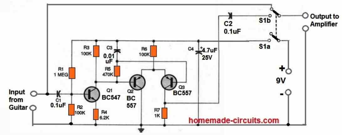
With this type of gain, the guitar music is amplified to a range which can operate the next stage. The next stage is supplied to the differential BJT pair of Q2 and Q3, which is biased as a limiter.
R5 and C3 comprise the RC network, which serves a variety of purposes.
One benefit is that the AC signal at the base of Q3 is low-pass filtered, allowing the differential pair to obtain its DC bias from the output of Q1 instead.
The network additionally offers a base offset between Q2 and Q3 of around 30 mV.
This is essential for generating a greater proportion of even harmonics at low signal amplitudes.
Finally, when power is initially switched ON, the RC network induces Q3 to switch on steadily.
Because the Preamp would probably be turned on and off while hooked into the guitar amp, this keeps turn-on transients from getting to the output, which is crucial.
The circuit's input and output AC signals are coupled by the capacitors C1 and C2.
By providing power for a brief period of time before switching to audio, bypass capacitor C3 regulates the battery voltage and avoid turn-off transients.
R7 is selected is kept small in value, in order to balance the levels of the "on" and "off" signals and to cut down on distortion in the signal route between the device and the amplifier.
How to Test
Turn on the power after connecting the distortion circuit to a guitar and an amplifier.
Adjust the amp's volume and the circuit's volume to produce a clear, largely undistorted guitar sound.
Then pump up the guitar volume level until the distortion also gets louder.
Here, you might need to dial down the amp volume a bit. Play an open string while briefly turning the distortion circuit on and off.
The loudness in both stages should be identical, and the transition should be silent and seamless.
Once you complete the above settings, you're prepared to rock and roll, or play anything you would want with with your guitar strings.
However, you must first attach the circuit board to the guitar body. In the article's prototype, the board was attached to the guitar body using a dab of silicone sealant.
However, there are other approaches you might want to try. If you want to follow suit, be sure to operate in a space that is well-ventilated.
Additionally, wait about 24 hours after applying the glue before covering the enclosure with a lid because while the glue cures, fumes are released that might harm the electronic parts.
After experimenting with the equipment for a period, you might be happy to discover that the distortion preamp circuit causes very slight distortion, when your guitar volume is trimmed down.
However, the distortion level might start sounding more like a swarm full of bees once you increase the volume up.


Need Help? Please Leave a Comment! We value your input—Kindly keep it relevant to the above topic!