The post investigates a cheap Chinese made 12V, 1 amp MOSFET based smps circuit which can be modified into 24V 1 amp, or 12V 2 amp smps circuits also. The MOSFET used is STB9NK60Z which is a highly advanced, rugged 600V 7A device specially manufactured for high, unpredictable, voltage environment circuit applications.
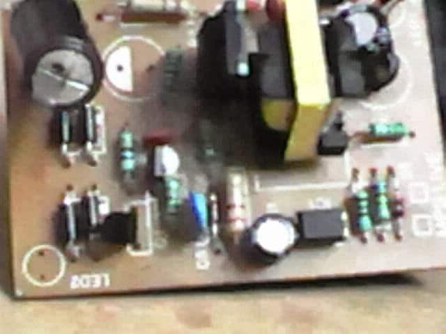
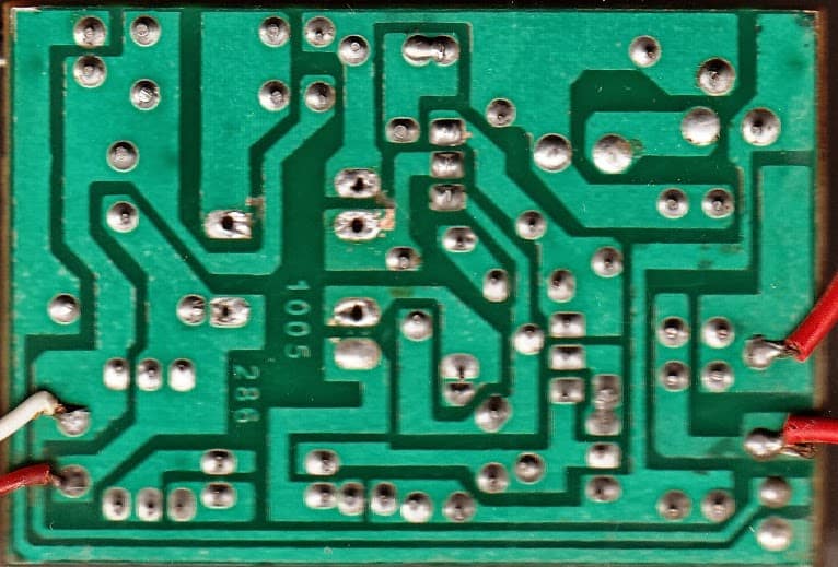
Reverse Engineering a 12V 1 Amp SMPS Adapter Physically
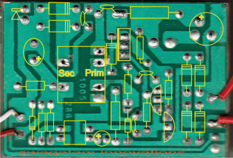
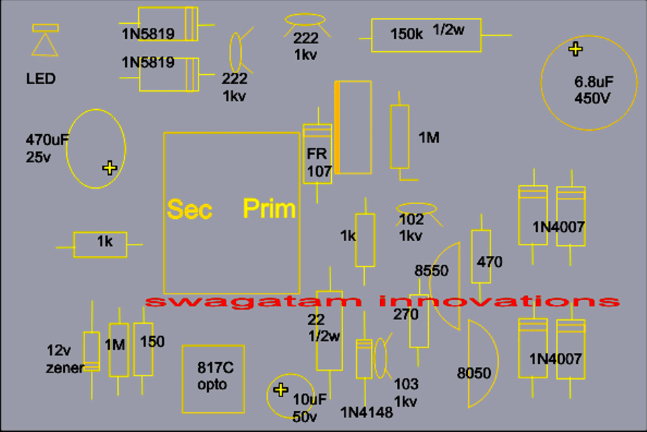
Coil Details:
The proposed 12V, 1 amp MOSFET based smps circuit utilizes a single E-core transformer, the winding details may be understood from the following info:
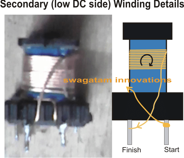
Wire thickness for the above secondary winding = 0.6mm, no. of turns = 12
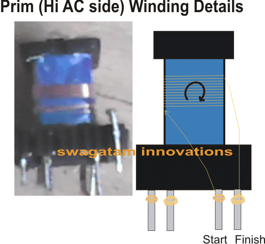
Wire thickness for the above primary winding = 0.25mm, no. of turns = 12
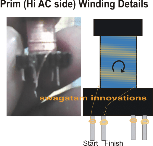
Wire thickness for the above primary winding = 0.25mm, no. of turns = 170
Feedback from one of the dedicated readers of this blog Mr. Debabrata Mandal:
I bought one today which is exactly the same, well, almost, cost me 100₹
Tested it @shop for 10 sec & it ran fine, brought home, plugged it in & was just about the test it with multimeter & there was a popping sound, though the indicator led was still glowing
Opened it and found that the electrolytic @ 12v side had blown, another 16v cap was burnt, in this condition I tested the output & found output at around 22-23v
Right now, I cannot check it properly because as soon as I turn it on, within a second the mosfet starts getting burning hot.
Also I can't figure out the transistors s9014 & s8550, what type or how their pins are configured?
There are just 3 components different than the above design
100E/.5w instead of yr 150e/.5w (resistor)220e instead of your 270e (resistor) s9014 instead of your s8050 (transistor)
Without taking anything out of the board, I tested the diodes/zener, they looked fine to me.
So without taking out the transistor/mosfet could you tell me how to check them w/o having to turn the power ON... because that could melt the mosfet for sure.
Or whatever idea you can share to debug this... also, how do i tweak the circuit to 14v (13.6~14.4) & 1.1A (>1.05)
Possible Solution:
The mosfet should not become hot as long as the output is not loaded or short circuited.
If it's getting hot without any load at the output could mean a faulty primary section.
Confirm the status by doing the following steps:
Cut the PCB tracks of the secondary winding terminals such that it becomes completely isolated from the circuit board, confirm the continuity with a multimeter.
Next connect a 25 watt bulb in series with the input AC to the smps and switch ON power. If the 25 watt bulbs glows or if the mosfet shows significant heating would confirm a faulty primary stage.
The next step would be to remove the transistors one by one and replace them with new ones and apply the input voltage to check the mosfet condition.
If the heating persists then finally you can go for a mosfet replacement with a new one.After all these procedures are completed and the problem is fixed, we can go ahead to check why the secondary is generating a 24V output.
This could be due to a wrong winding data or may be once the primary stage is resolved as above, the output would also settle down with the correct output.
More Inputs from Mr. Debrata
OK I already took out the 2 transistors + mosfet + transformer and checked all looked fine, checked the resistors and capacitors, all seem to be fine and then I put them back & started checking the pcb itself...
I found a short, after soldering they didn't cut short that leg & it protruded & touched the copper film, so i cut it short & checked, now the output showed2.3v but still mosfet kept getting Hot.
Amazing... finally nothing to do, i replaced the blown cap with 1000u/16v keltron and what? The problem got fixed.
Analyzing the Issue
Wow that's indeed very interesting., so the problem was in the filter capacitor, once it got fixed, the opto-coupler could receive the feedback input from it and in turn helped to regulate the mosfet conduction.....
Anyway all's well that ends well.
Thanks for the feedback.


Questions & Answers
In the primary side after change bridge rectifier s8050,s8550 ,fqp6n60 mosfet and resistances i have no dc voltage on secondary side. when I change 8050 and 8550 with bc547 and bc557 I met only 3.4 voltage what’s the reason behind this Sir pls can you tell about this.
Hi Amarjeet, I guess you might have connected the 8050/8550 pins incorrectly. The collector/emitter pins of the BC547/BC557 and 8050/8550 pin are exactly opposite. So please check this, and confirm the polarity…
Sir, Can you please share the Circuit Diagram and working of this power supply ?
I am unable to understand , how switching (chopping) of primary is taking place through MOSFET?
I mean which part of circuit generate PWM pulses ?
so sad, can you please tell something about working of this SMPS ? I want to know PWM part ….why transistors are connected in this way ? collector to base etc please help
You can refer to the following SMPS design, it may help you to understand the basic working of a transistorized SMPS circuit:
https://www.homemade-circuits.com/32-v-3-amp-smps-led-driver-circuit/
Hello Sanjay,
Sorry, presently I don’t have the schematic diagram for the above SMPS design, if I find it will try to update it here soon.
Hi, I have 3 units. All with burnt bottom two recitier diodes, blown 8550 and 8050 transistors, and burnt MOSFET. Unable to diagnose exact cause. Is there a cicuit avaliable for this module?
Hi, You can try cleaning the board and check for all the possible burned parts, and then replace them all with new ones. After this you an connect a series 100 watt bulb with the input and switch ON the SMPS. If the bulb remains shut off then you might have repaired it correctly, otherwise there may be something seriously wrong. I do not have schematic of this SMPS
Dear sir, pl. suggest me for 24v 2 Amp SMPS circuit using MOSFET. i want to make and sell this SMPS for R O machine. my whats app No. is 9977477407
Dear Nitin, you can modify the above SMPS circuit to get 2 amp current by using a slightly thicker wire for the secondary winding.
You can use two 0.6mm wire strands and wind the turns with both the strands held together, simultaneously.
hello sir how have I upgraded this smps to out put 24v at 12Amps. am stuck my load is 24v 11amps DC. thanks
Olupot, I don’t think a 12 amp modification would be possible from this circuit, unless thorough calculations are done for achieving the inductor dimension and the mosfet rating correctly
Please send me the circuit diagram of 12v 1amp MOSFET smps circuit.
NAMASTE, SWAGATAMBHAI MUJE IN PUT 12V STEP UP SMPS -40V GND +40 CHAHIYE AAP MUJE NAMUNA BANAKKAR DE SHAKTE HAI SIR ? MERA CO. MO. 9426923636 HAI NAM GUNUBHA GOHIL GUJRAT DIS. BHAVNAGAR TALAJA PIN 364140. AABHAR SIR AAPKA BHAI GUNUBHA GOHIL
Hello Gunubhai, I am sorry, sample bana kar dean possible nahi hoga, aap neeche dikhaye gaye circuit ko try kar sakte ho, kisi experienced electronic engineer ka help lekar.
https://www.homemade-circuits.com/2014/06/smps-2-x-50v-350w-circuit-for-audio.html
Thanks for circular
Please can you suggest changes fir 5v and 9v output
Sorry I am not sure about that because I have not yet studied the circuit deeply…however it may not be recommended to change anything in the original design
Sir, will the circuit performance will remain unaffected if we use 103/lkv instead of 102/1kv.
Please suggest
thanks, will look after suggestion
Dear Sumeet,
That's very strange, winding with parallel secondary wires should increase current….make sure the wires are thin and seamlessly merge within each other and fit tightly inside the bobbin…if the parallel wires are not cleanly wound and do not blend smoothly then that might create opposite results.
Dear sir
Thanks for circuit is working great..
As i increases the secondary wire thikness or added parallel two wires.. the 'Amp' decreases.
Can suggest solution
Thanks for information..
From market i have a similar circuit..
But has few changes
1. In place of 150k 1/2w they usr 100k 1/4w
2. 2A272 in place 222/1k
3. And 1.5e 1/2w in place of 22e 1/2w
Thanks Sumeet, slight changes might be possible for different versions, depending on the manufactures research and improvements…
that's also possible but 7805/7809 option is much safer and easier to implement
Ok..
But this had modify the circuit.
Can simply changing 12v ziner to 5v and 9v works?
use 7805 IC at the output for 5V and 7809 IC for 9V
Sir, the transformer winding is first primary winding then secondary winding,
Are you right sir
Salam, do it as suggested in the images, refer to the title of the images.
Dear sir,
Kindly tell me the part number of the mosfet also note that it seems the 22 ohms 1/2watt resiator is connected to the source of the mosfet which you have not shown.
Regards
Jayanta
Hello Jayanta, the mosfet number is given in the top paragraph of the article. I can see the 22 ohm ohm resistor clearly shown in the layout diagram.
Thanks a lott…
Dear,
Is it that the mosfet in the shown smps is taking the switching pulses from series connected transistors to drive the trafo?
i want to know working difference between transistor and mosfet,
according to me, i feel that mosfets cannot switch on/off on their own, they need a low current switching pulse at their gate and amplify it then send o/p to drain and to trafo……is this right??…….just want to clear this thought.
According to me, when a transistor is used for switching, it does not necessarily need any switching pulses from any oscillator circuit, it directly starts switching as it gets input power taking simple example of a joule thief circuit.
In the joule thief circuit, the transistor is switching the trafo on its own…..but what if there were a mosfet in place of transistor? would switching action take place or not?
Dear, please correct me if i'm being misunderstood.
Thanks
Dear Sherwin,
Your assumption are incorrect.
The mosfet and the transistors along with one of the primary winding of the transformer become an oscillator circuit. Basically it's the mosfet and the trafo primary which become the main oscillator components, the transistors are just for assisting the mosfets in the process.
Transistors also required external osculating frequency just like mosfets, transistor have no power or property of oscillating alone without an external configuration.
in a joule thief the transistor oscillates due to the feedback from the coil winding, the above smps may be also running on the same principles.
mosfet require 10v to trigger optimally so if the joule thief is powered with above 6V then probably a mosfet would also work
Dear,
I have the following queries;
1. What is the idea behind insertion of paper or keeping an air gap between the two core pieces in ferrite trafos?
actually, i've opened various smps power supplies and tried to study their config…..i noticed some trafos had a paper stuck between the core pieces, some had air gap and some had
nothing between the core pieces, stuck firmly.
Hence, please help me…… in what way should i make the config and which config is proper, since i'm rewinding the trafo for the emergency tube light circuit.
The trafo is quiet big……salvaged from an 12v 5a smps and managed to remove the core pieces, here it was an EI core type. this trafo had a thick paper between the core pieces.
2.Secondly, does it matter whether i wind primary first or secondary second or vice-versa, and what about winding direction of both coils?
3.Again, which winding configuration is more efficient at the primary of trafo, a two wire or a three wire?
Please help.
Dear Sherwin
the paper ensures a gap between the ferrite core joints and restricts them from getting stuck magnetically while the inductor is in operation.
The gap is crucial, if it's not maintained will cause the magnetic effect to go beyond the correct optimization point and lead to "shorting" of the effect.
This will result in the inductor functioning at much lower saturation levels and below the optimal points.
No it doesn't matter which winding is wound first, primary can be wound over secondary or secondary over primary according to me.
two wire configuration is more efficient
Please let me know the size of above PCB and the schematic diagram
I did not draw the circuit diagram,
the PCB design can be directly made and the parts assembled as directed in the directly.
sir where is the circuit diagram of above board
you can judge it by comparing the components sizes
Dear Sir
Please let me if I want to purchase the above circuit diagram complete with assemble please quote me the rate my qty will be 100-500 per month on regular base. We are manufacturing medical equipements and we are using same circuit purchasing from local market in adaptor cabinets please quote us the rates so we can purchase from you.
Regards
Ketan Khakhar
email: krupaelectrodevice@gmail.com
mobile: 09409648515 / 8153084584.
Ketan, you can try modifying the zener diode value for getting a preferred voltage at the output
Sir I want 24v what changes I have to do
I hope you've read my email response, the above comment is the continuation of the email which I sent you.
Ketan, you can get it from Lamington Road in Mumbai, for less than Rs.90/- but with the cabinet.
Sir from where can I get the Circuit Please let me know I want 100Pcs Urgent
My Mobile No is +919409648515 / +918153084584
Regards
Ketan Khakhar
Dear Ketan,
Thanks for the offer!
The cost will be around Rs.60 per piece, without the cabinet.
sir please publish the schematic for this circuit
I'll try to do it, if possible.
Can I calculate amp of this board using a multimeter?
yes you can do it.