In this post I have explained how to build a simple laptop power bank circuit which can be used for charging a laptop battery during travelling or during outdoor trips.
This device can be specifically useful on situations or places where an AC mains outlet is unavailable or difficult to find.
Why Laptops Need a Battery
Just like mobile phones, laptops are also portable gadgets that require a battery to operate when there's no mains AC supply is available.
This is the main advantage of laptops over PCs since a laptop can be carried with us while travelling and can be operated from anywhere outdoors.
This becomes possible because a laptop has an in-built battery. The battery provides the required power supply to the device whenever needed, and allows the laptop to work without the need of an AC mains supply outlet.
Laptops are so portable and handy that these can be opened and operated by anybody on top of their laps, and hence the name laptop.
Which battery is used in Laptops
In most of the cases the preferred battery for a laptop is a Li-Ion battery.
Li-ion battery batteries are one of the most efficient types of batteries with a very high power-to-weight ratio.
Power-to-weight ratios signifies that the battery is capable of providing long backups at high power rates through relatively smaller light weight packages.
The voltage specifications of a laptop may vary for different laptops.
Some laptop may work with a 11.1 V battery some laptops may work with 14.8 V battery and some other types may work using batteries with higher voltage rating.
The average current rating of a laptop battery may be around 4000 mAh which can provide a backup power for a period of approximately 4 hours.
In this post I have explained how to build a laptop power bank circuit for a laptop using a 11.1 V Li-Ion battery.
The 11.1 V laptop battery uses 6nos of Li-Ion cells each rated at 3.7 V. The 6 cells are configured as 3S2P, meaning, two parallel sets of batteries each having 3 cells in series.
The mAh rating of each cell could be around 2000 mAh. Therefore two parallel sets would result in a total mAH rating of 4000 mAh.
Since there are 3nos of 3.7 V Li-ion cells are involved, the total voltage of the laptop battery becomes:
V = 3.7 + 3.7 + 3.7 = 11.1 V
This 11.1 V value is the level where the battery is at around fully discharged state.
Since the full charge value of each 3.7 V Li-Ion cell is 4.2V, the total value of a fully charged 11.1 V laptop battery would be:
V = 4.2 + 4.2 + 4.2 = 12.6 V
How to Build a Laptop Power Bank Circuit
The idea of the laptop power bank circuit is simple. We want to use a set of chargeable batteries in the power bank which has higher voltage specifications than the laptop battery.
This means, when the higher voltage from the power bank is connected with the laptop battery, the charge from the power bank battery starts transferring into the laptop battery. This continues until the laptop battery is fully charged and the power bank battery is discharged.
Since the laptop battery has 2 parallel sets of batteries with 3 series cells on each set, we will use a higher configuration of 4S2P. Meaning our power bank will have a 2 parallel sets of battery with each set having 4 cells in series.
With a configuration of 4 series cells, the total fully charged voltage of our power bank circuit will be:
V = 4.2 + 4.2 + 4.2 + 4.2 = 16.8 V.
Each cell can be rated 2000 mAh, which will allow the configuration to have a specification of 16.8 V 4000 mAh.
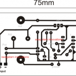
The complete connection diagram of the laptop power bank battery can be seen in the following figure:
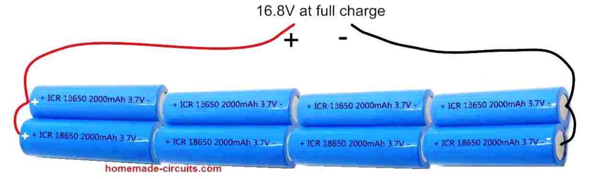
In the above figure we can see how a 4S2P (4 series, 2 parallel) combination of Li-Ion cells are configured to build a power battery pack of 16.8 V.
Specifications of each of the cells used in the battery pack are as follows:
- Li-Ion Cell = Type 18650
- Voltage = 3.7 V
- Capacity = 2000 mAh
Using Voltage Regulator
Although now we have an easy laptop power bank set up ready with us, the 16.8 V output is not safe to be directly applied to a laptop battery. Therefore, we need a voltage regulator that would regulate the 16.8 V into a constant 12.6 V.
For this we yet again rely on our work horse regulator IC LM338.
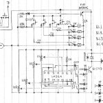
Using IC LM338 and a few other passive components we can build a very efficient, full fledged laptop power bank charger circuit, as shown in the following figure.
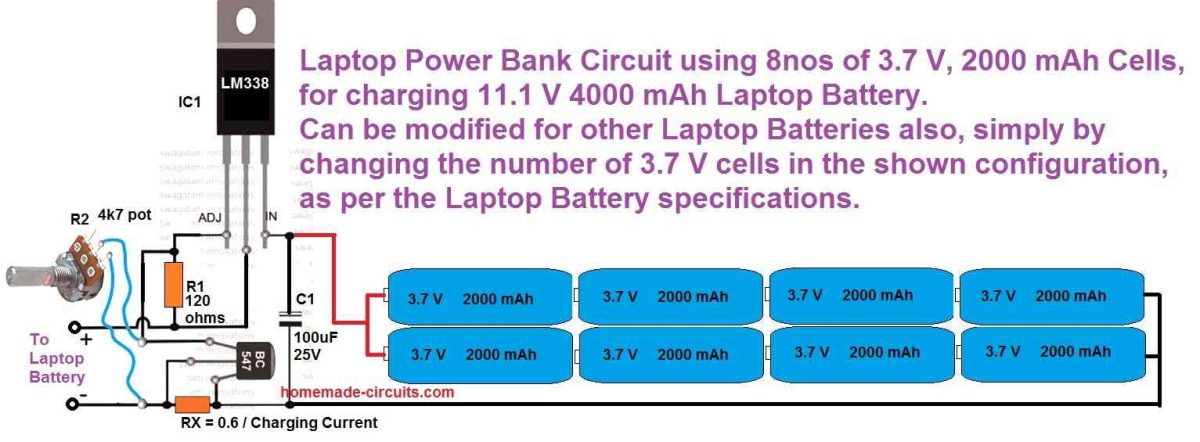
In the above design, the potentiometer R2 should be precisely adjusted to get 12.5 V at the output which can be then used for charging a laptop battery.
Although the full charge level of an 11.1 V laptop battery is 12.6 V we must adjust the output from the LM338 to precisely 12.5 V which is 0.1 V less than the full charge value.
This ensures that the laptop battery can never get over charged even if the power bank circuit is connected indefinitely with the laptop battery.
Calculating the Constant Current Resistor
Another aspect that Li-Ion batteries are typically critical about is the charging current which must be constant and limited. That's exactly why RX is positioned in the above shown LM338 circuit.
You will have to adjust the value so that it limits the current to a constant 0.5 C value which is equivalent to 50% of the laptop battery's mAh rating.
The value of the RX can be fixed using the following formula:
RX = 0.6 / 2 amp = 0.3 ohms
wattage = 0.6 x 2 = 1.2 watts or simply 2 watts
Make sure to apply a good heatsink on the IC LM338
The 0.6 V signifies the turn ON voltage of the BC547 transistor. When the current consumption tries to exceed the 2 amp value, it causes a voltage of 0.6 V to develop across the 0.3 ohm resistor which in turn causes the BC547 to switch ON. When the BC547 switches ON it shorts the ADJ pin of the LM338 to ground shutting it off. Shutting off LM338 at 2 amp consistently, prevents the charging current from exceeding the 2 amp mark.
How to Charge the Power Bank?
That's a valid question.
Before you can take the power bank unit with you for charging the laptop battery, you have to make sure the power bank battery is itself fully charged, otherwise it won't serve the purpose.
The idea is simple, construct another LM338 voltage regulator same as the one shown in the above image. However, since the power bank battery pack's full charge voltage level is 16.8 V, the output voltage from the LM338 regulator must be adjusted to a precise 16.7 V.
The complete circuit diagram for the power bank charger can be witnessed in the following figure.
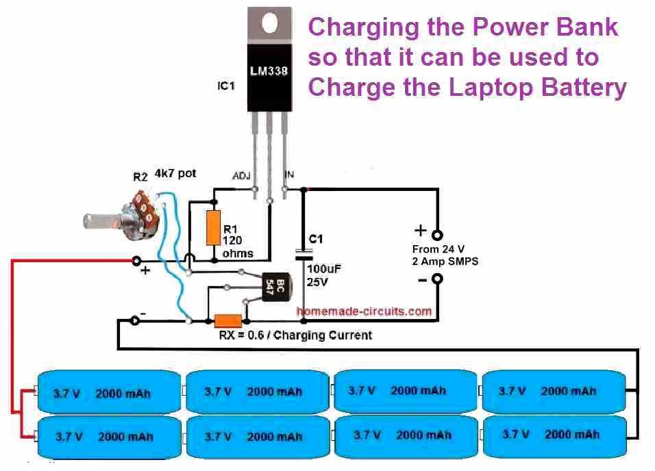
Again, here too we adjust the charging voltage 0.1 V less than the full charge level of the battery to make sure the battery pack never gets fully charged.
This concludes our article on how to build a laptop power bank circuit, if you any further questions please let me know through the below comment box, I will try to solve your queries ASAP.

Questions & Answers
Hello, when charging Li-Ion and Li-Po rechargeable batteries, the best method for the health of your battery is not to exceed the maximum voltage specified by the manufacturer. Some users have tried to reuse over-discharged and sleeping Ni.Cad. batteries by waking them up with a short-term shock voltage of 2…2.5 times the battery voltage, but when it comes to Li-Ion and Li-Po batteries, digging and hammering methods damage the battery irreversibly, so I will talk about a method I found practically. Li-Ion and Li-Po. battery voltage-X-1.135, in other words, 3.7X1.135=4.19995 for a 3V7 battery. A 3.7V series connected battery becomes 7.4V, its charge limit voltage is 7.4V X 1.135 = 8.399, which makes 8.4V, e.g. 6 X 3.7V = 22.2V X 1.135 = 25.197V, which means 25.2 Volts is the applicable upper limit voltage. I hope this information was useful.
very useful, thank you very much for the enlightment.
I have damage lots of batteries without considering the required voltage going in.
Thank you very much for this very interesting and valuable information.
I am sure the readers will find this information very useful.
You are welcome Mr. Swagatam, when it comes to standard 3.7V batteries, the upper limit is calculated simply by multiplying the number of 4.2V batteries. The reason I wrote the 1.135 formula here is to simply calculate the maximum voltage for a battery with a non-standard voltage. I will give an example (for a specially produced 17V Li-Ion battery, 17X1.135=.19.295V. You can charge it with a maximum of 19.3V). Of course, as you know, the right thing to do is to use a c.c-c.v. charging circuit that complies with the limit values.
Thank you very much Mr. Ali, I appreciate the valuable inputs you have provided so far!
Yes, I understand the principle you have applied.
Actually I already used this principle for lead acid batteries and it works nicely as a benchmark for calculating the full charge levels of all other battery voltages, in the same category.
I have discussed the working principles of lead acid and Li-ion batteries under these posts:
Lead Acid Battery
Li-Ion Battery
Hi Dear Swagatam;
I have scrap drill motor with the battery pack (13 * 1.2V each 800mAh). Its battery charger adaptor is input 24V 300mAh and output 18V. When I test it battery pack it is charged in a short period and discharged in short period too on the load. It seems that voltage value (for each individually about 1.26) is OK but the power / current is weak (to my opinion). Could you please advise that I should change all the 13 bateries or is it possible to check each and to supply the necessary in return for the defective ones?
Hi Suat,
You can try checking each cell separately using a flashlight bulb. Or may be by connecting two cells in series and then checking with a 3V flashlight bulb. If the bulb illumination is optimally bright then those cells could be assumed to be good.
Thanks so much Swagatam, sorry that battery amount is not 13 but 15 pcs (15*1.2= 18V) and also I have realised after the above message that there are ripples in the 24V adapter and the osiloskop shows VP 34V and 100 Hz. So I will change the filter capacitor of the charger adaptor and then recharge the battery pack. Is it possible to hope that the battter may be good in this situation?
No problem Suat,
But 34 V looks too high for a 18V battery. Also if these are NiCd batteries then the max current should be limited to 10% of its Ah rating. The actual results can be confirmed only after 10 hours of charging cycle.
thanks for the info, multimeter shows the voltage as around 22V but osiloskop shows VP about 34V and AVG voltage is just 18V because of the fluctiation. Please check the video of the youtube.com/watch?v=Irnlckla65Q&t=26s (about 72V 8A battery charger by electr10ic) since we have published this video and mentioned about your site. I also remain for your critics
Suat, according to my knowledge the peak voltage must not be higher than the full charge level of the battery. So if your battery’s full charge level is 22V, then the peak DC charging input must be also restricted to 22V.
Is this your You tube channel?
I understand Swagatam thanks, the only point I need to understand is that this voltage format type with the ripples is normal or the charger unit is defective? Yes the channel is mine but published by my relative.
Yes, ripple voltage can be used to charge batteries, in fact ripples help to keep the battery desulfated, so definitely the charging voltage can be with ripples, but the peak voltage must not exceed the full charge specification of the battery.
Thank you so much for all your help. Please I just constructed a power bank of my phone using battery arrangements of 3s35 , each cell 3.7v , 2000mah . Please sir how can I modify this your circuit to charge the battery from AC supply. To get balance regulated voltage, current and maybe indicator to shows it fully charged. thank you sir I appreciate your kindness assistance.
if i may ask we building power bank like this i can not see any AC pot there so that when the batter gets low and we will be able to charge it.
Can you please explain what you mean by an AC pot?
Hi Baatey, what is 3S35? Do you mean 3S3P?
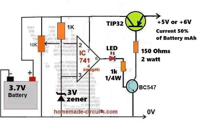
You can use the following circuit to charge your battery, however it does not have a balance charging feature.
For the current control you can add a LM338 based current limiter at the supply input side of the circuit to restrict the current to the desired level.
Hello Swagatam,
Thank you for publishing this tutorial! It makes sense to me.
My question is how to build a charger for 4S 5P battery pack?
Have built the battery packs and added BMS to the 5 4S packs.
Need to build charger for these. Can you advise please?
Thank you,
Bill
Thank you Bill,
4S means the maximum charging voltage of the pack should be 4 x 4.2 = 16.8 V
To find the total mAh rating of the pack, you can multiply the mAh rating of a single battery with 5.
So the recommended charging current will be 50% of the above result.
Using the above results you can configure a charger suitable for your 4S 5P battery pack.
Hello Swagatam,
Yes 16.8 V and 4000mAh x5 20000mAh. Now you say 50% of the Ah is sufficient, correct?
My thinking was 2o amp. Would that be too much?
Hi Bill,
yes 50% or 0.5C is the recommended rate. So for your setup, it should be around 10 amps.
At 20 amps or at a 1C charging rate your battery would charge much faster, but that might also cause the battery to heat up.
However, since you have a BMS attached, the heating and the charging rate would be automatically managed, so i think 20 amp should be fine.
Nevertheless, I would recommend testing the results through a practical experimentation.
Also, another question.
My design concept is to use a microwave oven transformer, with modified secondary winding. As I was aiming at 20 amp charge rate, it was decided to wind the secondary with copper strip in order to get ~17VAC out of it. This was to facilitate my 16.8V 4S packs. I purchased 15mm x 0.010″ copper strip for this.
A rogue calculation was that the strip could deliver the 20 amps.
Is my guesstimate close?
And how would one regulate the current to 10 amp in the charging circuit?
Thank you again
I am not sure about the copper strip current handling capacity,, it will need to be confirmed with some practical experimentation.
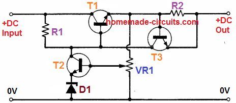
For voltage and current control, you can use the following basic concept:
The values of the parts can be customized as per the specifications of you application.
Hi Swagatam,
Thank you for the direction. This appears to be an achievable circuit design for me. Now I am assuming the transistors are or should be MOSFET such as IRFZ44N. Would you have a recommendation for this?
And should 1 be a voltage regulator?
Thank you for your help :^)
Thank you Bill,
For T1 you can use the transistor 2N5686,
https://www.mouser.com/datasheet/2/308/2N5684_D-2309214.pdf
R1 can be around 33 ohms 1 watt.
T2 and T3 can be 2N2222, D1 = 3.7V, potentiometer or preset VR1 = 10k
R2 = 1 / 10 = 0.1 Ohms
R2 power = 1 * 10 = 10 watts
Hi Swagatam,
Found all the components (had some of them), yet finding a 3.7V zener diode proved unavailable. Ordered 3.6V diodes. Thinking this should work. Would any adjustment be needed in the circuit elsewhere?
That’s great Bill,
The 3.7V capacitor at the emitter side of T2 is not crucial, it simply decides the minimum achievable output voltage. A 3.7V zener would not allow the output minimum voltage to be lower than 3.7V and so on. So you can rather eliminate that zener diode and replace it with a short, which would allow you to get a minimum voltage upto 0V.
No other adjustments are required.
To test the variable voltage output from the circuit, make sure to put a 1k or a 2.2k, or a 4.7k dummy load resistor across the output terminals of the circuit.
Thx Swagatam!
I will work on this when I have some time :^)
Now to figure out what to use for insulation on the secondary winding. Thinking of getting Varnished Cambric Tape. In your opinion, would this be sufficient?
Sure, no problem Bill.
Yes, the “Varnished Cambric Tape” looks good and can be used as an effective insulation for transformer windings.
… also, have built a rectifier bridge using Schotkey diodes (what I had, 15A), a reluctor that was recovered from something I scrapped some time ago, and 2 470uF 50V caps. It seems to do be functioning well. Have the components for the regulator board, have been busy with other tasks lately. Will get back to it when time allows.
Thank you for your time and advice!
No problem Bill, all the best to you!
Hi Swagatam,
Got the microwave oven transformer secondary wound with the copper strip. Upon testing, the transformer heats up. Not sure of the temps, just that without load after about 10 minutes it was quite warm to the touch. Have read that MOT by design is not optimal and noise/heat is not unusual.
Any thoughts on this?
Hi Bill, All transformers are similar with their characteristics. The noise and hum in a transformer will depend on its size and how well the winding and the laminations are clamped. Since MOTs are high current and bulky devices there might be some noise, which is normal. However if it dissipates heat above 50 degrees C without load, then something may be wrong with the winding. Also with a load, the heat must not exceed 60 or 70 degrees C, according to my knowledge.
Hi Swagatam,
Thank you for the explanation.
I have basic knowledge and have built simple rectifier circuits using diodes and capacitors. I also know there is much more to a proper circuit to be used as a charger.
Where could I find detailed information on constructing a proper charging circuit?
Thank you
Just read more on your site. You are a hero! Rescues make the best companions! My wife and I have nothing but rescues as household pets. We have been together for 13 years, adopted 3 rescues the first year and another the following. 2 dogs and 2 cats. We lost 1 cat last year and 1 dog early this year. Since we adopted another dog from the shelter.
I have long been an animal lover as has been my wife.
I wish you success in your dreams sir!
That’s awesome Bill, I truly appreciate that. The best thing that you can do in your life is to save and rescue these helpless creatures.
More than worshipping God, focusing on following a noble path is truly meaningful.
I wish you and your wife all the best on your journey with this exciting endeavor!
Hi Bill,
As far as I know, a constant current (current limited) and constant voltage with auto cut off is more than sufficient for any Li-ion battery charging. I do not currently have a BMS kind of charger details with me.
I want to ask can the regulator regulate it to 3.5 for charging of phones?
Yes it can regulate to any voltage between the 1.25V and the maximum input supply voltage (-3V)
Hello Swagatam.
By your explanation if I have a battery that in total has 11.1 VDC, consisting of 6 batteries of 2000mAh each, connected 2 by 2 together in parallel, and these 3 parallel connected in series (3S2P) we will have such 3.7+3.7 +3.7= 11.1 VDC nominal.
Please clarify, I still don’t understand.
What will the total capacity be 2000X2= 4000 mAh or 3X4000 = 12000 mAh?
Another example: 3 batteries of 3.7 VDC 800 mAh each, all connected in series, with the same 11.1 VDC, what will the total capacity be 800 mAh or 800X3= 2400 mAh?
Thank you in advance.
Best wishes
Hello Joao,
When battery is connected in series the voltage increases but the current remains the same, and when connected in parallel, the voltage remains the same but the current increases.
So in your first example the total current capacity will be 4000 mAh, and in your second example it will be 800 mAH.
Hello Swagatam, thank you for your reply.
So I can say that if I have a battery with 11.1 VDC and 4800mAh total, consisting of 6 batteries associated in 3S2P, to know the capacity of each battery when there is no more marking beyond 18650, just do the following arithmetic operation of 4800/2 = 2400 mAh, because each parallel is made up of 2 batteries, and in the case of 3 in parallel, divide by 3 and so on?
Thank you in advance.
Best wishes
Hello Joao,
In parallel connection the current capacity increases.
In your example the current will be 4800 x 2 = 9600 mAh
Hello Swagatam, thank you for your reply.
Ok. So I’ll ask the question another way, (English is not my mother language).
On a 11.1 VDC 4800 mAh (nominal) 3S2P connection power bank. How can I know the capacity of each battery in the set when each of them only has the reference 18650?
Thank you for the clarification Joao,
I think I misunderstood your question. I thought that the capacity of each battery was 4800 mAh.
If the 4800 mAh is the rating of the entire power bank (3S2P) then yes you are right the capacity of each battery will be 4800/2 = 2400 mAh
Thank you for your fast reply.
Best wishes
Good day , you said I will need to bulid another circuit to charge battery as well can a someone connect 220v to the input of circuit that will charge the battery .?
Sorry, I cannot understand your question. Can you show me the comment where I suggested you to build a charger, I can’t seem to find it.