Although, a 7805 IC is mostly used as a fixed 5 V voltage regulator, it is possible to configure a 7805 IC to produce a variable output from 5 V and higher, depending up the input DC supply. In this post I have explained a simple circuit network which can be used for getting an adjustable output voltage between 5 V and 15 V through the IC 7805.
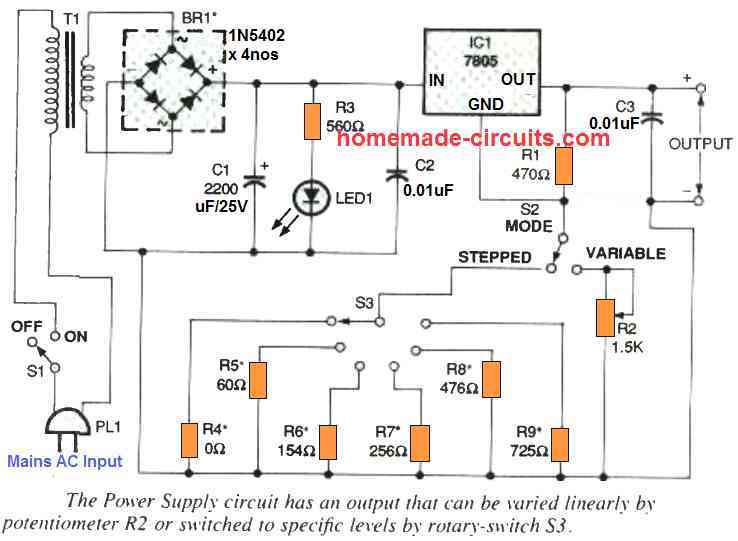
The following figure shows the circuit diagram of the variable IC 7805 power supply. The simple design provides you a range of voltages (which can be adjusted as desired by the user). The circuit can also generate up to 1 amp output current which is a much bigger than most small AC adapters are rated to produce.
How the Circuit Works
As indicated in the diagram, the output voltage is ranged between 5 V and 15 V DC. As soon as power button S1 is switched on, the mains AC is applied to the transformer T1.
This transformer steps down the voltage around 18 VAC, which is subsequently full-wave rectified through a bridge-rectifier BR1.
The capacitor C1 is employed to clean up and smooth the 100 Hz ripple generated by the bridge rectifier, and the charge stored in C1 is delivered to the voltage regulator.
The remaining capacitors, C2 and C3, behave like bypass capacitors which further condition the voltage delivered to the IC 1 which is a 7805 voltage regulator. In general the majority of the circuits working with a 7805 regulators apply them for generating a fixed 5 volts.
However, in circuit design explained here, enables the output from the IC 7805 to be adjusted roughly between 5 V and 15 V (although, as mentioned, 15 volts.
The following description helps us to understand how the proposed IC 7805 variable power supply works: Typically, an input supply voltage greater than 5 V is fed to the input pin of the IC.
The ground pin of the 7805 can be normally seen as connected to the ground line so that it is able to regulate the OUT pin to 5 volts level which is 5 V higher than voltage level at the ground pin held at 0 V.
However , when ground pin of the 7805 is lifted by a certain voltage over the ground level, this lifted potential will add up with the 5 V and cause the output to increase by a level which is lifted at the ground pin of the IC.
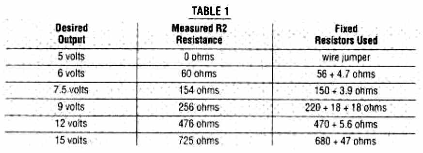
In this IC 7805 adjustable power supply circuit, the center ground pin of the IC is fixed through a resistive divider created from a resistor R1 along with R2 which is a variable resistor or through one of the selectable resistors ranging from R4 to R9.
Each of these six resistors configures the output to a certain precise voltage level as determined by the values of the resistors. When the potentiometer R2 is employed it enables an entirely adjustable output from 5 V and the maximum 15 V.
Let's imagine that switch S2 is selected to use the potentiometer R2 in the voltage divider network. Here, as the 7805 IC1 attempts to keep up precisely 5 volts at its output, the voltage at center ground pin of the IC could be adjusted by varying the resistance of the lower half of the resistive divider via R2.
Consequently, the output voltage is consistently switched to 5 V plus the voltage developed by the R1/ R2 divider network at the center pin of the IC1.
As the process causes the output of the IC1 7805's to increase, this also causes the voltage at the resistive divider junction to increase, which in turn forces the output voltage to increase, and and process keeps going on and on, until the input voltage "exhausts".
This is exactly how the 7805 regulator gets converted from a fixed 5 V regulator into a variable output regulator.
When you toggle the button S2 so that it hooks up with the center GND pin of the IC1 and the rotary switch S3, and S3 is used to select one of the resistors from R4 to R9, these resistors now take the position as the bottom half of the resistive divider.
The values of these resistors between R4 and R9 can be selected in a manner that the output can be fixed to generate precise voltages from 5 V, 6 V, 7.5V, 9 V, 12 V, or 15 V DC. The following table can be used for selecting the fixed resistors to obtain the respective variable outputs from the IC 7805
5 V to 13 V Using 7805 and Op Amp
The next variable 7805 circuit is similar to the above design, but it is more reliable due to the involvement of an op amp.
The voltage is obtained through R2 and RV1, that are wired across the stabilized output to ensure that regulation efficiency is not considerably reduced. This voltage seems to be too large in impedance to operate pin 3 of IC1, therefore a basic buffer amplifier based on IC2 is used to bridge the two. R1 represents a ballast resistor.
The CA3140 device was selected for the IC2 slot because its output is able to go down to within a few millivolts of the negative supply voltage.
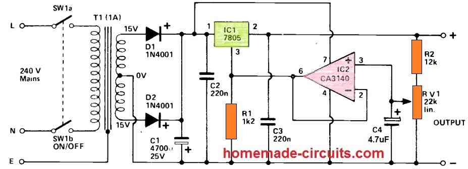
In contrast, several options, including the 741C device, provide a minimum voltage of no less than 2V, resulting in the lowest output voltage of 7V from the 7805, which becomes inappropriate for use with TTL and several other forms of circuits.
A traditional push-pull type step-down, rectifier, and filtering circuit provides the input voltage for the regulator circuit.
C2 and C3 contribute to the circuit's reliability and therefore should be placed as near to the regulator IC as feasible. C4 smooths the voltage at the RV1 wiper and contributes to the circuit's low output noise level of around a millivolt. The output drops by only 70mV between zero load and maximum power, indicating excellent regulation. The 7805 IC includes current limiting functionality that prohibits output currents over 1A from flowing.
Questions & Answers
Hi Dear Swagatam;
I have the 7805 which looks like the 2N2222 transistor and I am not sure which pin is input pin. Although as known the generally pin1 is the input, is there any tips to distinguish that?
Hi Suat,
I have never seen a 7805 IC in TO-18 package like 2N2222. Also there’s no online information about this.
I am not sure if it is available in that package or not.
So it is difficult for me to tell about its pinout details.
can you make a variable power supply which can be charged and then use it.I think I can use 3 or 4 lithium ion batteries
Input : 9v
Output : 25v
can you boost the voltage without using inductors and using capacitors.
If you can can you suggest a circuit that makes a capacitor store its charge for about 1hr
I don’t think a good boost converter can be built without inductors, so that’s not possible.
Greetings … thanks for the diagram … it is ingenious and very useful … but it seems that there is a small error in the drawing when joining the lower end of the 470ohms resistor R1 with the lower end of the 0.01 mf capacitor C3, then if so, the selector resistors and the potentiometer would be shorted and inoperative.
Respectfully.
You are absolutely correct. The diagram was taken from a magazine, and it seems the magazine people failed to notice this error….I will soon update the diagram with a new one…thank you for pointing it out
Sir engineer Swagatam
Hello dear. I am deeply believe that you are a very honorable human being. Thank you for so generously helping others. I congratulate you for so being good. Your Circuit titled “Variable Voltage, Current Power Supply Circuit Using Transistor 2N3055” is excellent and simple to assemble. I have all the components at home.
Thank you again and wish you all the best in the wold.
Truly
Mehrdad
Thank you Mehrdad, glad you liked the idea!
Sir engineer Swagatam
Hello. Thank you very much for this excellent circuit. I wish you designed it in a way that we could have 0 to 15 V output which would be a complete bench power supply for most of your site audiences. Thank you anyway.
Truly
Mehrdad
Thank you Mehrdad, since the minimum output from the IC 7805 wll be 5 V, so it cannot be reduced below 5 V, however if you are looking for a bench power supply, then you can easily build one of these circuits, and customize as desired.
How to Design a Bench Power Supply Circuit
Variable Voltage, Current Power Supply Circuit Using Transistor 2N3055
A good project, but it would be better if it had an adjustable current control and a current indicator led
Thank you, yes a current control would be great, it could be probably added using one of the concepts explained here
2 Best Current Limiter Circuits Explained