In this post I have explained a simple electronic temperature regulator circuit which could be specifically used for regulating greenhouse temperatures. The idea was requested by Mr. Leo.
Technical Specifications
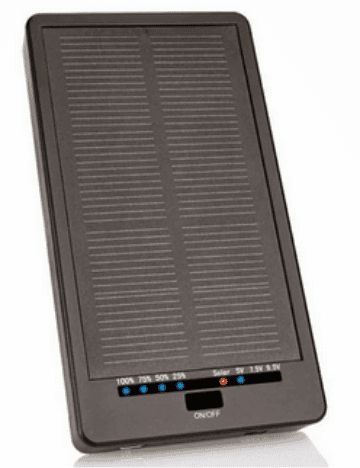
I am looking for a guide to build a basic temp regulator circuit. I have a solar charger bought from lidl,(SLS 2200 A1) which has outputs for 5, 7.5 & 9.5v DC 0.5A. it will be used for soil heating in a greenhouse.
My idea is to use black drip irrigation pipe as a 'solar panel' to heat the water and with a low volume pump regulate the temp under a propagation tray. Any advise is greatly appreciated.
I have seen similar setups for egg incubators , fridge temp controls, etc. but need it at an allotment, so only power source is small panel. also if possible would it be possible to increase capacity of internal battery and have a heating element added.
Thank once again.
Leo
Introduction
Before getting into the main circuit concept, it would be interesting to learn regarding a few of the parameters expressed in the above request, as given below:
What is "black" drip irrigation:
We all probably have heard a lot about drip irrigation, a method in which water is fed to the crops across the entire allotted field through a network of narrow pipe lines wherein water is allowed to drip directly at the bottom of the stem of the crop for a sustained period of time. The method helps to save water and allows the water to reach the crucial areas such as the roots of the crop resulting in a better growth and efficiency.
Here an identical approach is implemented but the conventional pipes are replaced with black coiled PVC pipes. The back coiled pipe helps to absorb the heat from the sun rays naturally and allow the water passing through it to become warm naturally without depending on costly artificial utility electricity. The warm water ultimately helps to heat up the soil deep inside for acquiring the intended greenhouse effects.
What's a Propagation Tray:
These could be arrays of plastic plantation pots arranged in a large tray like fashion for allowing deeper soil content to the seedlings over minimal spaces, it's specifically designed for optimizing indoor plantations.
What's Allotment:
It may refer to a small garden or a plot of land as explained here:
https://en.wikipedia.org/wiki/Allotment_%28gardening%29
The Solar Panel: The specified solar panel is a self contained unit which includes a solar panel with outputs at 5,
7.5 & 9.5v DC (0.5A). It also includes a 4-step charge indicator circuit and most interestingly it includes a built-in 2200mAH Li-ion battery so that you don't have to bother about external battery integrations, rather would be able to use the existing facility under overcast conditions.
Basic Requirement for the Green House Effect
Now let's return to the actual requirement of the proposed greenhouse temperature regulator circuit, the idea here is to sustain a raised temperature of the soil by 10 to 20 degrees Celsius above the atmospheric temperature for boosting or enhancing seed germination.
Because seeds normally germinate faster in soils that are warmer than the atmosphere, which in turn results in an initial stronger root development instead of bigger leaf development.
Generally, heat mats are used below the propagation trays for heating the soil but in the present application the drip water is itself heated and used for generating the same results, which looks much impressive, since heat mats could at times get messy causing sparks, fire or over heating of the soil (if the attached thermostat fails).
Nevertheless, the electronic temperature controller circuit discussed below could be used with any heating system, including heat mats.
In the proposed design, the natural heating of the water within the black pipes is aided by an external heating element until the temperature of the water reaches the optimal point. As soon as this threshold is sensed the heater is switched off by the regulator circuit and held at that position until the temperature falls back to a relatively cooler level.
Parts List
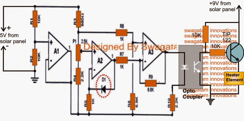
D1 = 1N4148,
A1---A3 = 3/4 LM324,
Opto = 4n35
Circuit Operation
Referring to the diagram above which is actually a simple temperature controller circuit, could well be used for regulating the soil temperature in the proposed greenhouse application.
Here the temperature sensor D1 is our very own "garden" diode (no pun intended ) 1N4148 which translates every one degree (C) rise in the ambient temperature into a 2mV drop across itself.
The opamp A2 is specifically arranged to detect this change in voltage across D1 and feed the difference to A3 such that the result illuminates the LED inside the attached opto coupler IC.
The threshold at which the above action takes place could be preset with the help of P1.
The output of the opto is connected with a NPN driver stage which is responsible for switching off the heater as soon as the above threshold is reached.
The sensor and the heater may be placed across any desired position, as per the user preference. For example the heater could be positioned below the propagation tray, or inside the water tank from where the water is being supplied to the black pipes.
On same grounds the sensor may be placed anywhere around, could be below the propagation trays, inside the soil, inside the pipe or simply inside the water tank.
The capacity of the unit could be upgraded as per the application, simply by employing a heavier rated solar panel and by replacing the TIP122 with a higher rated mosfet. The heater may also be upgraded as per the requirements.


Questions & Answers
Is there intact circuits for controlling Green house conditions: temperature, humidity, water flow (control irrigation pumps), lighting, supporting fans … etc
Sorry, I don’t have this circuit with me right now, will try to get it soon if possible.
Ok thanks for your reply. If you know any selling channel where I can buy such circuit please advise. Thanks
I think you should search it in amazon . com, you should be able to find some options.
Oh, here's an additional thougth for this setup; can there be an aditional set of temp/humidity sensors, and another pump setup as a spray. this would keep the humidity inside the greenhouse ideal. This seems like a setup that might be worth you patenting!
OK great. Let me do some thinking, I'll get back to you soon with the required data.
Patenting is a good idea, but the procedures are so tedious, it's worth only if it guarantees some good source of income,
anyway appreciate your suggestion! thanks
Found one on ebay, these are the detail tehy supply:
1 x RS-360SH Pumping motor
Simple gear-type pumping model, usually used for aquarium, DIY model etcs
Diameter: 2.7 cm
Length: 5.2 cm
Out of the water hole diameter: 4 mm
Rated voltage: 7.2V
Suitable for voltage: 3v-12v DC (marked with a red dot that Terminal is positive)
Seems ideal, but what do you think?. Still looking for a valve system, don't know where to begin!?!? i guess miniture butterfly actuators would be overkill for this.
not sure what valve system? but will look at some model shops for specifics.
OK, no problem!
Black irrigation pipe:
The GARDENA Supply Pipe 4.6 mm (3/16") is the supply pipe for Drip Heads and Spray Nozzles. It is UV-resistant and impervious to light, thereby guaranteeing long use. It can be installed above and below ground. The length of the pipe is 15 metres.
I think you have de-cyphered the other references. If possible could two additions be made.
1) a low volume/flow pump will be needed to circulate the heated water, as convection will not be enough.
2) a simple valve system which isolates a hot water system from the cold. ( hot would be the pipe run on outside of greenhouse frame, the cold from a 100 litre water butt.)
Yes the additions could be done, please provide the voltage and amp specs of the low volume pump and the valve system, and if possible also provide the type of valve system you would want to use, may be by a code number etc.just as you have provided for the solar panel.