The ZSD100 is an alarm frequency generator IC which incorporates a frequency swept alarm signal generator designed solely for fixed and vehicle protection alarm systems.
Circuit Operation
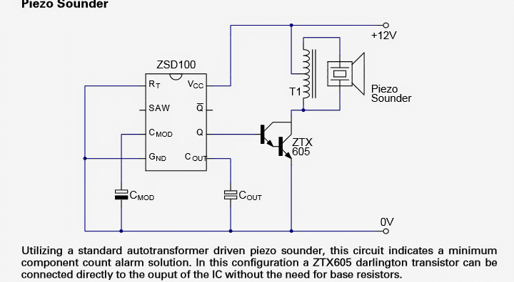
For acquiring the specified alarm sound from this IC, just a single ZSD100, two timing capacitors, an in-expensive TO92 darlington, piezo transducer and coupling transformer is everything that becomes necessary to generate an extremely loud, ear piercing 120 dB warning siren.
Together with an acoustic frequency signal generator, low frequency sweep generator, shut down circuitry and output driver stages, the ZSD100 has been attributed with all functionality crucial to generating an approved alarm indication.
You may get this IC with a choice between an 8 pin DIL or SO bundle the IC grants an inexpensive stream-lined approach to siren signal technology. The system may be powered from inputs of 4V as much as 18V which specifically becomes suited for security detectors in battery driven products, burglar alarms and vehicle anti robbery techniques
FUNCTIONAL Information
The acoustic indication of the ZSD100 is created employing a squarewave oscillator whose operation is competent of directly triggering numerous output circuits. To generate a peculiar alarm siren sound, the frequency of the audio oscillator is swept over an allocated 2:1 spectrum by another, lower frequency oscillator. The frequencies of both the oscillators are regulated by R T (INT) and capacitors C MOD and C OUT
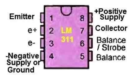
PINOUT DESCRIPTIONS
Pin#1. RT: Non-obligatory superficial resistor for enhanced frequency management. An peripheral resistor boosts the domination of each the modulating and output oscillators. The RT pin is furthermore employed to energize the gadget down. Possibly attaching RT to VCC or an open circuit would probably bring about the device getting crippled.
Pin#2. SAW: Choice of modulation waveform is done employing the SAW pin. An open circuit generates a triangle wave, sawtooth is accomplished by joining SAW to the CMOD pin.
Pin#3. CMOD: An exterior capacitor would be used to program the low frequency modulating oscillator. The worth of CMOD advisable is between 0.1μF and 10 0μF.
Pin#4. GND
Pin#5. COUT: An secondary capacitor would be used to program the output oscillator. The value of COUT endorsed is between 1nF and 100nF.
Pin#6. Q Non inverted output driver
Pin#7.Q Inverted output driver
Pin#8. VCC
Alarm Circuits Using ZSD100

Questions & Answers
Hi Swagatam,
I tried the 100uF cap and zener diode and several combinations with no success. I have one 9v battery that has 7.35v and one with 7.43 volts and one with 8.2 volts. I tried each of them and the 7.35 volt works great. The others don’t. I also tried 5v and 6v with no success. The ZSD100 appears to be two sensitive to voltage to be useful for me. I have a CK9561 siren chip and I am using it to drive the piezo/inductor circuit with very good results. I’m just very disappointed with the ZSD100. Thanks for your help.
Thanks Norman, for updating the results, I hope the readers will find it useful!
Hi Swagatam,
I have built the first circuit above using a BC517 transistor. I used a 10uF electrolytic for CMOD and a 103 for COUT. I am powering it with a 9v battery. The piezo sounder came out of a smoke detector. It is a three wire piezo. I am not using the feedback connection. I am using a 3-pin piezo boost inductor. The unit is very loud(119db) at about 6″. The problem is the ZSD100 does not oscillate correctly. I tried changing both capacitors separately. Using a 682 and a 22uF it tweets rather than whooops as I would like. Using a 333 it buzzes. Same thing with a 104. Using the 103 and 10uF it whooops but gets hung up on the high end of the whooop. It does the same thing with a 153. This one is actuated by a switch. I built another one that uses a lm358 proximity circuit to actuate. It actually whooops (sometimes) using the 103 and 10uF. It is off when set on a table and whoops when lifted off the table about 3″. If I lift it to 5″ or 6″ off the table it quits whoooping and just screams. I know this sounds strange, but it does exactly this. I’m thinking the resonant frequency of the piezo is somehow affecting the ZSD100. I thought you might have a suggestion what else to try.
Hi Norman, It could be the back emf spikes from the inductor which may be interfering with the IC functioning. You can try adding a 100uF capacitor right across the supply pins of the IC and also a 9V zener diode across the supply pins, hopefully this might help to solve the issue.
O.K. I managed to look up the weapon article and saw that Radio Shack transformer. Thanks again……….I’ll have a good look at that.
I am glad your could solve it…simpler buzzer concepts can be also read under the following articles:
https://www.homemade-circuits.com/simplest-piezo-driver-circuit-explained/
https://www.homemade-circuits.com/how-to-make-simple-piezo-buzzer-circuit/
Hi Swag, thanks for the quick reply! It’s that transformer that confuses me. I’ve seen quite a few circuits similar but no-one explains what the transformer actually is or a spec with part number etc. I would prefer some or other off-the-shelf part if possible. Thanks.
Just btw, on the overunity stuff, it is all very interesting but close to impossible. If you go to the Revolution Green website http://revolution-green.com/ they have a panel of experts that explain all of the phenomenon that sometimes makes us think that overunity is possible, and also can do some actual work. Mark Dansie and his team of really open-minded experts have been debunking most of the so-called overunity gadgets for many years. I love this subject myself and keep thinking about the possibilities.
You are welcome Keith! The transformer is a readymade unit and works just like any other step down transformer. One side has a lower number of turns while the other side has many times more number of turns. It can be used as a step up or step down transformer depending on how its winding are configured with a circuit.
Yes the overunity subject is hugely fascinating and enticing, I hope somebody picks up the concept from my article and succeeds in debunking it. My view too is very skeptical regarding such concepts.
Hi, in this piezo sounder circuit, you mention a standard auto transformer. Can you supply the specs and/or where to get a suitable one? If I need the output to be in the 20 ~ 30 KHz range then what value of transformer inductance would I need? Thanks very much!
Hi, the specs can be seen at the bottom of the following article:
https://www.homemade-circuits.com/how-to-make-ultrasonic-weapon-usw/
actually no special IC is required for driving a piezo, any ordinary oscillator circuit could be used for the purpose