This simple, enhanced, 5V zero drop PWM solar battery charger circuit can be used in conjunction with any solar panel for charging cellphones or cell phone batteries in multiple numbers quickly, basically the circuit is capable of charging any battery whether Li-ion or Lead acid which may be within the 5V range.
Using TL494 for the Buck Converter
The design is based on a SMPS buck converter topology using the IC TL 494 (I have become a big fan of this IC). Thanks to "Texas Instruments" for providing this wonderful IC to us.
You may want to learn more about this chip from this post which explains the complete datasheet of IC TL494
Circuit Diagram
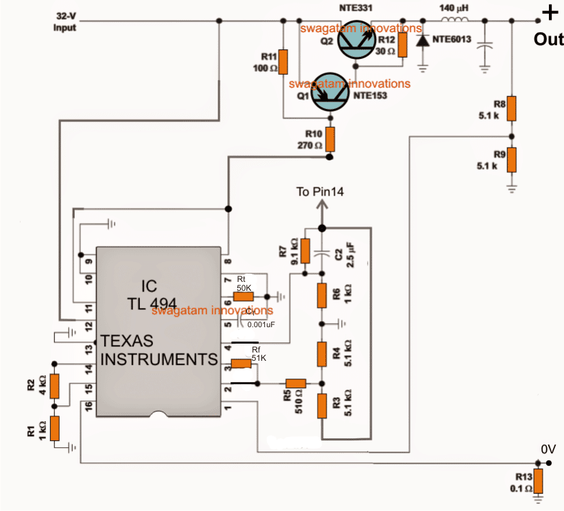
We know that a 5V solar charger circuit can be easily built using linear ICs such as LM 317 or LM 338, you can find more info on this by reading the following articles:
Simple current controlled charger circuit
However the biggest drawback with these linear battery chargers is the emission of heat through their body or through case dissipation, which results in wastage of precious power.
Due to this issue these IC are unable to produce a zero drop voltage output for the load and always require at least 3V higher inputs than the specified outputs.
The circuit of the 5V charger explained here is completely free from all these hassles, I have explained how an efficient working is achieved from the proposed circuit.
Referring to the above 5V PWM solar battery charger circuit, the IC TL494 forms the heart of the entire application.
The IC is a specialized PWM processor IC, which is used here for controlling a buck converter stage, responsible for converting the high input voltage into a preferred lower level output.
The input to the circuit can be anywhere between 10 and 40V, which becomes the ideal range for the solar panels.
The key features of the IC includes:
Generating Precise PWM output
In order to generate accurate PWMs, the IC includes a precise 5V reference made by using bandgap concept which makes it thermally immune.
This 5V reference which is achieved at pin#14 of the IC becomes the base voltage for all the crucial triggers involved within the IC and responsible for the PWM processing.
The IC consists of a pair of outputs which can be either configured to oscillate alternately in a totem pole configuration, or both at a time like a single ended oscillating output.
The first option becomes suitable for push-pull type of applications such as in inverters etc.
However for the present application a single ended oscillating output becomes more favorable and this is achieved by grounding pin#13 of the IC, alternatively for achieving a push pull output pin#13 could be hooked up with pin#14, we have discussed this in our previous article already.
The outputs of the IC has a very useful and an interesting set up internally. The outputs are terminated via two transistors inside the IC.
These transistors are arranged with an open emitter/collector across the pin9/10 and pins 8/11 respectively.
For applications which require a positive output, the emitters can be used as the outputs, which are available from pins9/10.
For such applications normally an NPN BJT or an N-mosfet would be configured externally for accepting the positive frequency across the pin9/10 of the IC.
In the present design since a PNP is used with the IC outputs, a negative sinking voltage becomes the right choice, and therefore instead of pin9/10, we have linked pin8/11 with the output stage consisting of the PNP/NPN hybrid stage.
These outputs provide sufficient sinking current for powering the output stage and for driving the high current buck converter configuration.
PWM Control
The PWM implementation, which becomes the crucial aspect for the circuit is achieved by feeding a sample feedback signal to the internal error amplifier of the IC through its non-inverting input pin#1.
This PWM input can be seen hooked up with the output from the buck converter via the potential divider R8/R9, and this feedback loop inputs the required data to the IC so that the IC is able to generate controlled PWMs across the outputs in order to keep the output voltage consistently at 5V.
Other output voltage can be fixed by simply altering the values of R8/R9 as per ones own application needs.
Current Control
The IC has two error amplifiers set internally for controlling the PWM in response to external feedback signals.
One of the error amp is used for controlling the 5V outputs as discussed above, the second error amp is employed for controlling the output current.
R13 forms the current sensing resistor, the potential developed across it is fed to one of inputs pin#16 of the second error amp which is compared by the reference at pin#15 set on the other input of the opamp.
In the proposed design it is set at 10amp through R1/R2, meaning in case the output current tends to increase above 10amps, the pin16 can be expected to go higher than the reference pin15 initiating the required PWM contraction until the current is restricted back to the specified levels.
Buck Power Converter
The power stage shown in the design is a standard power buck converter stage, using a hybrid Darlington pair transistors NTE153/NTE331.
This hybrid Darlington stage responds to the PWM controlled frequency from pin8/11 of the IC and operate the buck converter stage consisting of a high current inductor and a high speed switching diode NTE6013.
The above stage produces a precise 5v output ensuring minimum dissipation and a prefect zero drop output.
The coil or the inductor can be wound over any ferrite core using a three parallel strands of super enameled copper wire each with a diameter of 1mm, the inductance value can be anywhere near 140uH for the proposed design.
Thus this 5V solar battery charger circuit can be considered as an ideal and extremely efficient solar charger circuit for all types of solar battery charging applications.
For Higher Voltages up to 60V Solar Panel
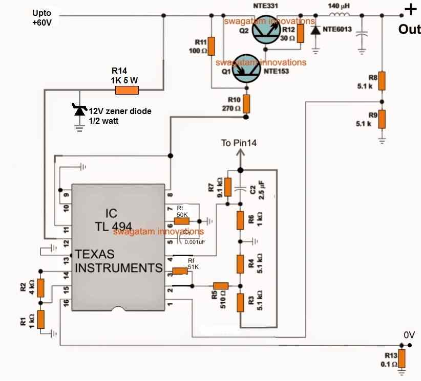
For solar panels with higher voltages, such as 60 V solar panels, the design can upgraded by adding zener diode regulator at pin12 of the TL494, as shown below:



Questions & Answers
Hello sir, I want a 3 stage charge controller with current adjust ( 0-5 A ) for 12V CCTV UPS to increase battery life, power voltage is about 13.8V and battery is 12V sealed acid, Can you help me to design this charge controller with transistor?
Hello Ruhollah,
I will design it soon and let you know…
Thank you, I will wait for your favor
Here’s the circuit diagram which i have designed, I will write the description also and let you know once it is finished:

Hello, Thank you for circuit design. how much the P3 and P4 Variable resistance? how much the most current that this circuit can support ( 5A or up )? please change circuit without current limit too.
I have added the full description under the following article, please check it. But i think the LM338 current limit cannot work using a single LM338 IC, instead you may have use two separate LM338 current limiter stages for the current limit #1 and #2:
https://www.homemade-circuits.com/make-this-3-step-automatic-battery/
Maxx current is 5 amp if LM338 are used.
Without current limiting won’t make sense in this design…
Hello, Thank you for Description about circuit, How much resistance that connect to input +14.5V And Tip3055 IC?
Hi, it can be 50 ohm 2 watt…
Hi, thank you very much for design the circuit, description that and reply all questions. I don’t forget your favor. Be in the protection of God
You are welcome!
Hello sir, it’s me again Daniel. So, it finally worked, but it charges the phone at a slow rate and it’s a 15w 12v solar panel. Is there anything I can do to increase the charging speed?
Glad it worked, Daniel,
You can try connecting two panels in parallel and check the response, or you can increase the power of the solar panel rating
Hello Mr Swagatam! I’m in a place where there is no electricity, so I took with me a 12v solar panel which I will use to charge my phone or a lead acid battery for storing power when I’m not around. I used a USB QC 3.0 DC-DC buck converter charging step down module which can take 6 to 32 volt maximum as the input and give out 5v as the output, so I then plugged in USB type C to charge my phone it indicated charging but the phones percentage wasn’t increasing. So what do I do?
Hello Daniel,
That means your mobile phone is not accepting the charge from the source.
Please confirm the output with a meter to ensure it is 5V DC, or you can add a 7805 IC at the output and check the response.
Hi Sir Swagatam! It’s me again, Charm! I already have this circuit produced in a PCB. For the transistors, I used TIP32C and TIP31A which are TO-220 package. The NPN transistor (TIP31A) heats a lot. And I will be converting 24V input to 5V output. I would like to ask you about heat sink recommendations and specifications that I could use.
Thank you Charm,
The transistor must not heat a lot, otherwise it would defeat the main purpose of a buck converter. Can you tell me the current specifications of your circuit…it shouldn’t be more than 1 amp. And did you use an inductor with the correct inductance value?
Hi Mr. Swagatam! the current of the circuit is 1A. I used the same inductance value of the inductance. When I put my battery as the load/ output. the transistor Q2 heats a lot that I couldn’t touch it.
Hi Charm, what is the battery Ah rating, is it drawing more than 1 amp? Also, check the input side voltage, if it drops significantly then your circuit might not be working correctly.
I have 2 batteries arranged in parallel. Each battery has specifications of 3.7V, 2600 mAh.
The input side voltage remains 24V when I turn on my circuit. The output voltage gives me a steady 5V.
OK, that means the current draw is much above 1 amp. Those two batteries can draw more than 3 amps if not restricted.
Try with a single battery and check the heat, if the heat is manageable that would clarify the circuit is OK.
In that case you can replace the TIP31 with a TIP35, and then use two batteries.
hi Sir! I tried with a single battery which has specification of 3.7V 2600 mAh. the TIP31 is still getting hot. Any recommendations?
OK, in that case, please try replacing only the TIP31 with TIP35, and check the response.
Sir, What should be the voltage and ampere of TIP35? I have seen 100V 25A, 80V 25A, 60V 25A
Charm, Since your max circuit voltage is 24V, you can use the 60V version.
Hi Sir! When my battery is fully charged, will this circuit cut the charging process? If no, can you please suggest a way to cut off the charging when the battery is fully charged. Thank you so much appreciate your help
Hi Charm, auto cut off is not included in the above design. However, an auto cut off may not be needed if you keep the full charge supply to the battery a shade lower, for example at 4.1V (4.2V being the full charge level for a 3.7V Li-Ion battery).
Anyway, with 0.125 amp supply input your battery may take ages to get fully charged.
Hi Sir! To achieve the 4.1V as my input voltage, do i need to add an external step-down converter to reduce the 5V to 4.1V?
For the solar panel, i will change my solar panel input that has more power to generate atleast 600mA. Thanks a lot!
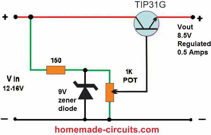
Hi Charm, you can add the following regulator at the output of your existing circuit. For the zener diode you can use 5.1V zener. Make sure to put a 1k across the output of this regulator while adjusting and measuring the 4.1v. Adjust the 1k preset for adjusting and getting the 4.1v output.
Hi Sir, I have an available buck converter module here, it uses lm2596. Can I use it to generate 4.1V? Thank you
Yes, you can use it to generate 4.1v, I had earlier suggested you the very same converter which is one of the easiest and most efficient.
Hi Sir! Please clarify the part where I need to put a 1k across the output of this regulator. Do you mean that after the Vout + and – I will put a 1K ohm resistor and after that will be my new Vout?
You are right Charm, It should be connected BETWEEN the Vout and the (-) of the previously linked circuit. The (-) of this circuit must be also connected with your PWM circuit’s 0V line.
Hi Sir! Do you mean, I will add a 1k ohm resistor after the Vout (+) and (-) of the PWM circuit. And after the 1K ohm resistor I will connect the Vin (+) and (-) of the voltage regulator using emitter follower transistor. And then connect my battery.
Hi Charm, you must connect the 1k across the emitter of the regulator transistor and ground. The output of the pwm circuit will connect with the input of this regulator circuit.
Hi Sir! 18650 li-ion batteries work with 1A current output. If I want to charge my 18650 batteries using this circuit, how can I generate 1A? I read the article that said its output current is 1A.
The output current will depend on the input current, and the inductor wire thickness. Please let me know how much input current are you suppling to the circuit?
Since I will be using a 1.5W 12V mini Solar Panel, my calculated input will be 0.125A. I am not sure if this current can trigger charging my 18650 batteries.
A 12V 0.125 amp input will not produce 5V 1 amp current, you will need at least 12V 600mA input to get 1 amp out.
hi Sir! I was able to generate 5V output with 24V input. My next question is, can I directly charge 2x 18650 li-ion batteries arranged in parallel with 3.7V using this circuit? If yes, what is the output current of this circuit to be able to charge the 18650 li-ion battery?
Hi Charm, Glad you could get the circuit working, and I hope you are now getting the intended frequency at pin#11 and pin#8.
You can charge Li-ion batteries using this circuit. The output current will depend on the input current.
Hi Sir. I will be testing the frequency at pin#11 and pin#8 at school tomorrow. I will let you know.
Sure, no problem Charm.
Hi Sir! I am thinking of the problem with my transistors and diode connected to my pin#8 and pin#11. I changed my transistors from NTE331/NTE153 to TIP31C/TIP32C. I changed the Diode NTE6030 to Schottky 45V 6A. And my capacitor is an electrolytic 2200 uF 35V. Can you advice if there is a problem when i connected this to my IC. I already changed my IC 2x to be sure my IC is not damaged.
Hi Charm,
Do one thing, remove the transistor connection from pin#8 and 11 and check the frequency without anything connected to these pins.
If still there’s no frequency then you will have to investigate the IC connections and configuration deeply.
Hi Sir! Do i need to connect pin#8 and pin#11 to VCC to test the frequency?
You don’t have to connect those pins to positive, just keep them connected with each other, and test the frequency across their junction and the ground, with a frequency meter.