This simple, enhanced, 5V zero drop PWM solar battery charger circuit can be used in conjunction with any solar panel for charging cellphones or cell phone batteries in multiple numbers quickly, basically the circuit is capable of charging any battery whether Li-ion or Lead acid which may be within the 5V range.
Using TL494 for the Buck Converter
The design is based on a SMPS buck converter topology using the IC TL 494 (I have become a big fan of this IC). Thanks to "Texas Instruments" for providing this wonderful IC to us.
You may want to learn more about this chip from this post which explains the complete datasheet of IC TL494
Circuit Diagram
We know that a 5V solar charger circuit can be easily built using linear ICs such as LM 317 or LM 338, you can find more info on this by reading the following articles:
Simple current controlled charger circuit
However the biggest drawback with these linear battery chargers is the emission of heat through their body or through case dissipation, which results in wastage of precious power.
Due to this issue these IC are unable to produce a zero drop voltage output for the load and always require at least 3V higher inputs than the specified outputs.
The circuit of the 5V charger explained here is completely free from all these hassles, I have explained how an efficient working is achieved from the proposed circuit.
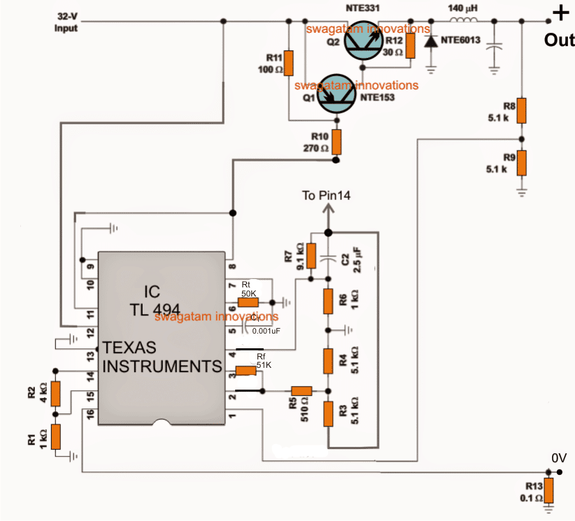
Referring to the above 5V PWM solar battery charger circuit, the IC TL494 forms the heart of the entire application.
The IC is a specialized PWM processor IC, which is used here for controlling a buck converter stage, responsible for converting the high input voltage into a preferred lower level output.
The input to the circuit can be anywhere between 10 and 40V, which becomes the ideal range for the solar panels.
The key features of the IC includes:
Generating Precise PWM output
In order to generate accurate PWMs, the IC includes a precise 5V reference made by using bandgap concept which makes it thermally immune.
This 5V reference which is achieved at pin#14 of the IC becomes the base voltage for all the crucial triggers involved within the IC and responsible for the PWM processing.
The IC consists of a pair of outputs which can be either configured to oscillate alternately in a totem pole configuration, or both at a time like a single ended oscillating output.
The first option becomes suitable for push-pull type of applications such as in inverters etc.
However for the present application a single ended oscillating output becomes more favorable and this is achieved by grounding pin#13 of the IC, alternatively for achieving a push pull output pin#13 could be hooked up with pin#14, we have discussed this in our previous article already.
The outputs of the IC has a very useful and an interesting set up internally. The outputs are terminated via two transistors inside the IC.
These transistors are arranged with an open emitter/collector across the pin9/10 and pins 8/11 respectively.
For applications which require a positive output, the emitters can be used as the outputs, which are available from pins9/10.
For such applications normally an NPN BJT or an N-mosfet would be configured externally for accepting the positive frequency across the pin9/10 of the IC.
In the present design since a PNP is used with the IC outputs, a negative sinking voltage becomes the right choice, and therefore instead of pin9/10, we have linked pin8/11 with the output stage consisting of the PNP/NPN hybrid stage.
These outputs provide sufficient sinking current for powering the output stage and for driving the high current buck converter configuration.
PWM Control
The PWM implementation, which becomes the crucial aspect for the circuit is achieved by feeding a sample feedback signal to the internal error amplifier of the IC through its non-inverting input pin#1.
This PWM input can be seen hooked up with the output from the buck converter via the potential divider R8/R9, and this feedback loop inputs the required data to the IC so that the IC is able to generate controlled PWMs across the outputs in order to keep the output voltage consistently at 5V.
Other output voltage can be fixed by simply altering the values of R8/R9 as per ones own application needs.
Current Control
The IC has two error amplifiers set internally for controlling the PWM in response to external feedback signals.
One of the error amp is used for controlling the 5V outputs as discussed above, the second error amp is employed for controlling the output current.
R13 forms the current sensing resistor, the potential developed across it is fed to one of inputs pin#16 of the second error amp which is compared by the reference at pin#15 set on the other input of the opamp.
In the proposed design it is set at 10amp through R1/R2, meaning in case the output current tends to increase above 10amps, the pin16 can be expected to go higher than the reference pin15 initiating the required PWM contraction until the current is restricted back to the specified levels.
Buck Power Converter
The power stage shown in the design is a standard power buck converter stage, using a hybrid Darlington pair transistors NTE153/NTE331.
This hybrid Darlington stage responds to the PWM controlled frequency from pin8/11 of the IC and operate the buck converter stage consisting of a high current inductor and a high speed switching diode NTE6013.
The above stage produces a precise 5v output ensuring minimum dissipation and a prefect zero drop output.
The coil or the inductor can be wound over any ferrite core using a three parallel strands of super enameled copper wire each with a diameter of 1mm, the inductance value can be anywhere near 140uH for the proposed design.
Thus this 5V solar battery charger circuit can be considered as an ideal and extremely efficient solar charger circuit for all types of solar battery charging applications.
For Higher Voltages up to 60V Solar Panel
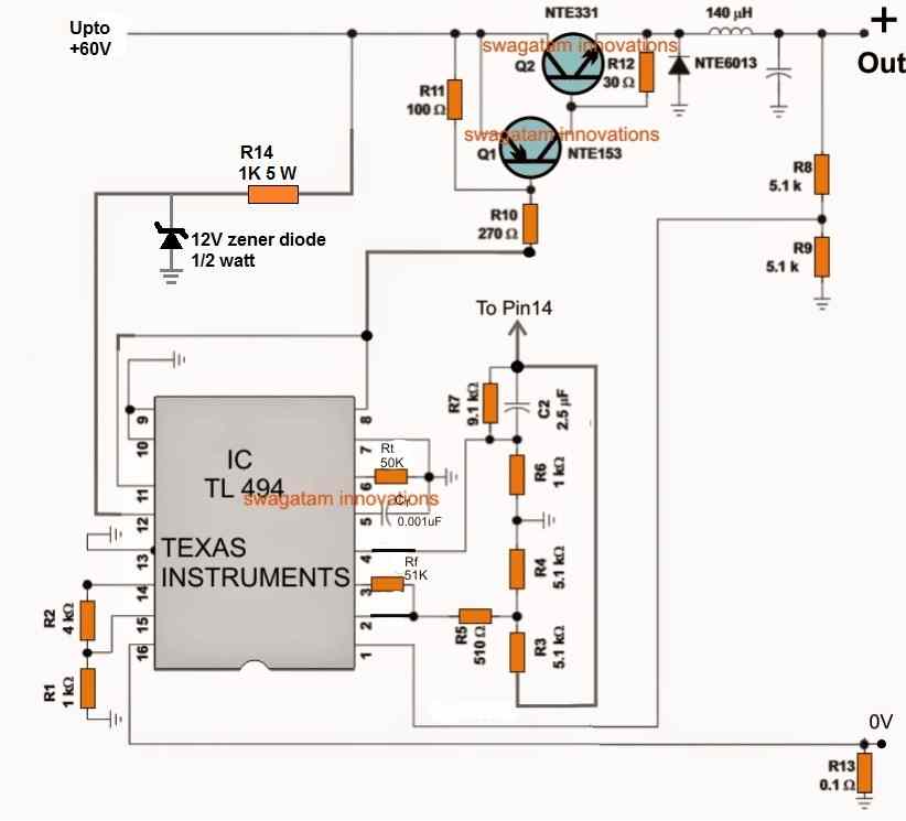
For solar panels with higher voltages, such as 60 V solar panels, the design can upgraded by adding zener diode regulator at pin12 of the TL494, as shown below:


Questions & Answers
I am gonna make solar projects. But never bought a solar panel. How much in rs the solar panel of 12v
you can easily find out the specs and the rates from any online source, there are plenty of them on the web….the cost will depend on the V/I specifications of the unit.
What about for 12V battery?
adjust R8
can you suggest a nearest value for R8?
you will have to verify it practically, you may replace it with a 10k preset and set it accordingly.
ok thank you..
Sir I want to know solar panel specification required for charging mobile battery
you can try a 8V, 500mA panel, but make sure to a voltage regulator with it
Hello Sir pls. Which of the resistors is the R8, Rt or Ref. Thanks
Please click the diagram to enlarge, and you will be able to locate them easily
hello sir , you have mentioned "to pin 14" at two points in cct diagram…..will u please define ,is the resistor configuration at pin 2,3&4 is connected to PIN 14 or what??
Same is the case with PIN 1 ??
waiting for your response ………
I'll correct the diagram and post it soon, thanks!
Ok Sir thanks a lot, but i have assembled almost all components……your guidance required in this regard…..as i got confused at the mentioned two points….
|| I have used TIP35A NPN and TIP36B PNP in place of NTE331&NTE153……is that ok??
||| If i skip 12Amp diode at output ,my required O/P is somewhere around 4Amp…..It will work for me ???
Instead of TIP36, I would recommend BD140 or 2N2907 or any other similar smaller BJT.
for 4amp requirement can replace the NTE6013 with a 6 amp fast recovery diode….the diode is a part of the buck converter and cannot be removed.
thanks sir,i got it ……diode is necessary part of buck converter……
Hello Sir,
The Cct was working fine
I used a 10K variable at R8…… and 9.1K at R2
O/P sliding between zero and input voltage (19V).
It charged four Li-Ion cells……. at constant voltage of 14.8 V.
Suddenly ,diode got short and Q2 heated up…..i replaced SB560 diode with YG911S3R but variable stopped working and O/P is varying B/W 19.2 Vand 18.1 V……….
Any suggestion plz……..transistors are fine TL494 is OK………
Hello beacon light,
check Q2 also, and if possible replace it with a new one.
a diode could become faulty if its current exceeds the safe operating limits….or probably if the device is a duplicate quality.
also make sure you have selected R13 correctly for proper current control functioning
Hello,
did you confirm the working of the circuit before using it with the battery? Any new circuit needs to be first confirmed with its voltage and current parameters before implementing it for the actual job.
This is a buck converter circuit with many crucial parameters which needs to be first verified using a multimeter and a dummy load.
If you are having difficulty optimizing the above design you can try a simple IC 555 based design as shown in the following article. try the second buck circuit:
https://www.homemade-circuits.com/2015/10/calculating-inductor-value-in-smps.html
you will need to optimize the pots perfectly in order to get the expected results
I am using this to step down 24v to 12v DC to dc…
Source 28v lion pack battery 40ah
…
Pls help me with the values of a variable resistor I need to adjust to gv me the adjustable output …
And sir how many amp can it handle at its output
Thank you in advance
you will have to do it by practically experimenting with the resistor values and simultaneously checking the output response.
the current will be 10amp if the mentioned BJTs and inductor are used…
Sir in these ckt 32v is input voltage (collector voltage of NTE331 ) and gate voltage the same transistor .
As far as my buck convertor input is 300v . So shuld i got 300v as gate voltage of my IGBT.
yes that’s right but make sure your IGBT is rated to handle that much voltage….to be safe do it exactly as indicated in the linked diagram, for Q1 you can use any ordinary PNP BJT such as STX93003
Hello sir, what is the maximum current of the circuit and how can i reduce it to the required current it want. Thanks
The current handling specs of the circuit can be reduced by using thinner coil wire, and by selecting BJTs matching the required output current specs….
Quick question about SMPS chargers. Since they have a fairly constant output voltage, if I wanted to implement a 3-stage charging algorithm, how can it be implemented with the constant output voltage nature of these Switched Mode Chargers?
Thanks.
for implementing 3-stage charging only the current will need to be modified at the various steps, voltage will automatically adjust as the battery gets charged
i have a inverter that has a momentary contact switch to turn on and the same to turn off (switch needs to be held for 2 to 3 seconds) i would like to hook this inverter to the thermostat of a freezer (i have already isolated the thermostat from the ac line) thanks so much for your blog i have fallowed it for a long time and made many of your ckts. bruce
Thanks Bruce, but this is a solar battery charger, it is not an inverter, you might have been mistaken
There was no mistake. i had to switch browsers for the java to work (thanks chrome) so i hit the first post comment i found when i switched to post my request. i need a ckt. that will give a 3 second pulse when a switch is turned on and a second 3 second pulse when the same switch is turned off ? thanks again!!!
OK it was actually my mistake I thought you were referring to the above circuit.
You mean to say you want a relay circuit which can be toggled ON for 3 seconds in response to a momentary push button pressing, each time this push button is pressed the relay will hold for 3 seconds and then go off….??
what i need is a 3 second pulse when a switch is turned on and a 3 second pulse when that same switch is turned off i will use this pulse and a relay to simulate a momentary contact switch turning something on and off thanks so much for your blog and your prompt response!!!
the switch is ON/OFF switch or a push button?
the switch is a standard on/off switch like a lite switch….. the device i need to control with it requires a momentary contact for 3 seconds to turn on…… and another 3 second momentary contact to turn off______ what i am doing is hooking an inverter to the thermosat of a freezer. i have disconected the thermostat from the freezer wireing but left it in the freezer i then wired the compressor always on if i have the thermostat turn the inverter on it will only have to be on when the freezer needs to be on !! way more eficent than having the inverter in stand-by until the freezer needs to come on. my problem is the thermostat as you know is thermoly operated but just a standard switch like a lite switch but the inverter is momentary contact 3sec for on 3 sec for off
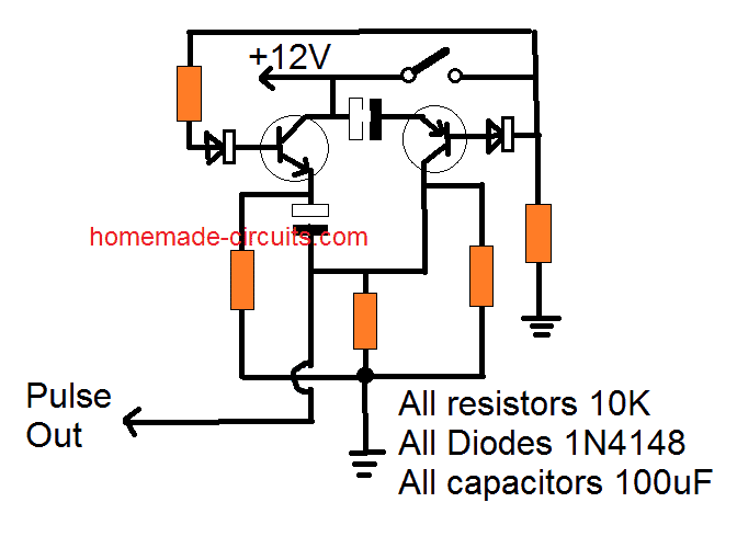
you can try the following concept
i am guessing we use bc 547 and bc557 thanks i will try it and see what transpires and i will let u know thanks again so much for your blog and especialy for your time bruce
yes that’s right, wish you all the best! the capacitor and the base resistor values will decide the output timing.
The diagram needs a correction, it should be in this way:
hello,
thanks for sharing. never came to the idea to use that for solar applications.
i used to create that circuit a while ago but was using bd244 and bd243 transistors. sadly the output voltage drops a lot even with light loads. do you have any idea or advice
Hi, Glad you liked the idea! In buck boost toplogies optimization becomes very crucial since the the output efficiency greatly depends on how well the coil and the PWM specs are adjusted. Next is the wire thickness and configuration which decides the current output. If all these are set correctly then the output is as intended otherwise it could go severely wrong.
Please how can I use this circuit for 100w panel for 12v battery
If your panel has higher voltage than 20 V, then you can use it
My panel has 18.65v
Is this at peak sunshine or average voltage
Peak
In that case you don’t need any converter. Just connect the panel directly to your battery.
If you intend to use one, you can try the above circuit but you may have to adjust the inductor turns a bit to optimize the output correctly.
ok sir, please how can i optimise the inductor coils, is it by adding to it or reducing
You can build the exact same circuit as shown above, and test it with a 24V/5 amp input from a power supply, and check whether it works or not as specified in the diagram. It should work because the circuit is designed by the ti.com engineers.
Once confirmed then you can gradually decrease the input voltage and proportionately reduce the turns and verify whether the optimization works or not.
can i use tip147 for nte331 and tip41c for nte153 and ba159 for nte6013. we dont have 0.001uf and 2.5uf what can i use
You can replace the transistors and the diode as mentioned by you, but the capacitors must be kept exactly as specified in the diagram to avoid confusions.