This transformerless mains power supply circuit will allow flashing of a Bi-color 100 LED string, in an alternately switching red, green effect.
Using 2-pin Bi-color LEDs
The proposed circuit can be used as a Bi-color LED flasher, for generating an alternate red, green flashing effect over a string of 100 LEDs.
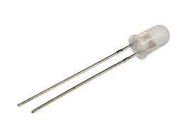
Bi-color LEDs are available in 3-pin and 2-pin variations, in our project we use the 2-pin Bi-color LED option for keeping things compact and much efficient.
Circuit Operation
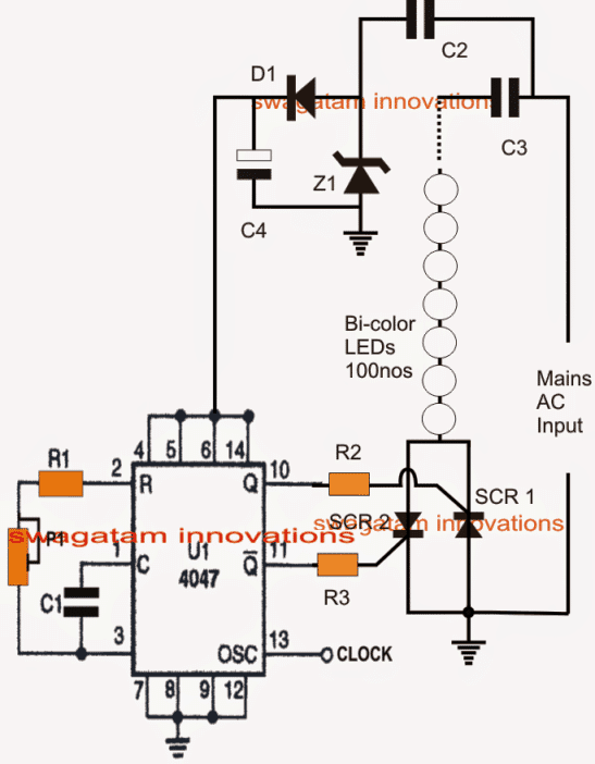
Looking at the design shown above, we can see a simple configuration using a push-pull clock generator IC 4047.
The IC is used for generating an alternately switching pair of outputs, from the shown pinout#10 and 11 of the IC.
The frequency of these alternately conducting outputs can be set by appropriately adjusting the pot P1 and by selecting the desired range with C1.
The switching outputs can be seen configured with two oppositely wired SCRs, which are in turn hooked up with the Bi-color LED string across the mains input through a dropping high voltage capacitor C3.
The circuit also incorporates a transformerless power supply stage consisting of C2, D1, C4, Z1, for powering the IC with the required low voltage DC.
When the proposed 2 pin Bi-color LED flasher circuit is switched ON, the IC starts oscillating at the set rate across its pin#10 and pin#11 alternately, driving the SCRs at the same alternating rate.
The SCRs respond to these pulses and conduct accordingly, enabling the Bi-color LED string to illuminate through an alternately green and red color flashing effect.
Caution: The above circuit is not isolated from mains, therefore is extremely dangerous to touch in an uncovered and switch-ON positioned.
Parts list
- R1, R2, R3 = 1K
- C1, C4 = 100uF 25V
- C2, C3 = 0.33uF/400V
- Z1 = 12V 1 watt zener
- D1 = 1N4007 diode
- SCRs = 2nos BT169G
- LEDs = 100nos (for 220V input), 50nos (for 110V input) of 2pin, Hi-bright RED, Green Bi-color LEDs
- Input: 220V/110V
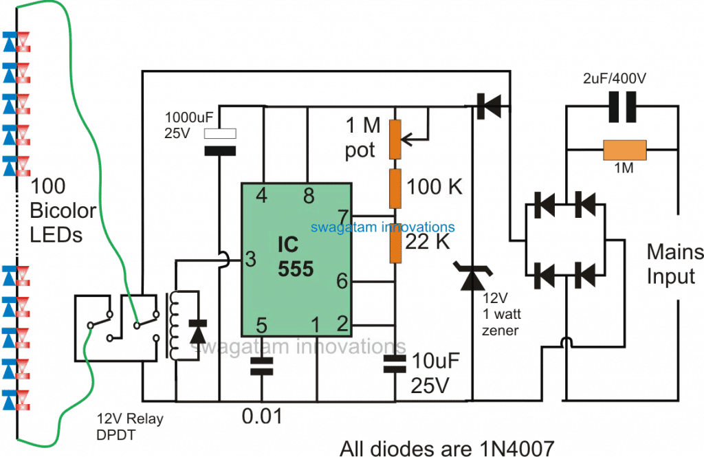
Correction Update
The design shown above has a serious flaw in it. The SCR1 is configured wrongly and might not conduct as proposed in the explanation.
The following diagram using an DPDT relay appears to be the correct approach for implementing the above discussed Bi-color LED flashing operations:
Two Color LED Blinker Using Neon Lamps
As seen in the following image, our next light string cycles between red and green at a consistent 1 Hz frequency, allowing it to be a lovely complement to any seasonal decoration. The process for changing colours happens as I have explained below.

A relaxation oscillator circuit made a couple of two neon lamps, NE1 and NE2, alternates back and forth at a rate of roughly 1 Hz.
The two color LED changeover rate is determined by R1, R2, and C3 numbers. C2 and D1 provide DC power to the neon oscillator circuit. DC filter capacitors are not employed or required.
When NE1 activates, current passes via an optocoupler in U1's LED, switching on the SCR and grounding D2's anode in the process.
Due to this , the LEDs get just the positive half of the AC waveform, which only illuminates the red LEDs (LEDs 1 through 30). After around one second, NE1 switches off, NE2 switches on, and U2 grounds the cathode of D3 as a result.
As a result, the LEDs get only the negative half of the AC cycle, which only illuminates the green LEDs. You may decrease the values of R1 and R2, and increase the value of capacitor C3 to decrease the frequency, in case you want to reduce the red/green alternating rate to less than one second.


Questions & Answers
Hello Sir, Can we modify the circuit with three push buttons one each for turning ON red LED, green LED and switching OFF.
I was planning to make a portable multi-color (red, green one at a time) blinking LED torch. It should be visible from at least 1km. Would a 3W SMD LED would be appropriate for it. Also it would be helpful if you could help me with the circuit.
Hello Akshay,
You can try the first circuit from the following article:
https://www.homemade-circuits.com/single-push-10-step-selector-switch/
Replace the relay coils with your LEDs.
Use TIP122 for the transistors
Hi Swagatam,
One of my friend request me to repair his bi-color (26 nos) LED series. It is china mfg low cost lighting operated in AC current through 4 diodes. Also there is Resistor attached with each LED. How the thing are working on that High voltage using only 4 diodes and resistors?
Hi Sunil, may be the resistor values are very high, could you tell me what value resistors are used? or you can investigate a little more and check what exactly are used in addition to the 4 diodes to step down the input current.
Hello sir i have 4 pin 8mm led full color sir i wanted to run 300 leds of that so u have any circuit for that
Hello Abdul, you can try the following concept
https://www.homemade-circuits.com/2014/04/simplest-100-watt-led-bulb-circuit.html
make 3 strings of 100 LED each, and connect them in parallel.
calculate the value of the input capacitor as per the current specs of the LED
Sir ,
I did the test twice, i have use bicolour but only shining red color. What will be my fault in this? I'm waiting for your advice.
Hi Satheesh, yes, SCR1 is incorrectly configured in the first circuit, therefore the circuit might not work, I have designed another one which is shown at the end of the article, you can try that….or alternatively you can try using a 3-pin Bicolor LED with the first circuit by inverting the SCR1 and a few other minor modifications.
Sir,
Good day to you I looked at doing this. However, only shining red color. Not two-color fluorescence What is the solution? So please provide you suggestion I have used c1 20k pot
satheesh, did you connect the ground of the circuit with the SCR ground?
and make sure both the outputs of the IC are oscillating.
and if possible first check the LED series manually by changing the supply polarity with an external DC power supply and check whether or not the LEDs illuminate with their specified twin colors?
Me again,
What type of modification could be applied to the circuit so that the leds are fading from one color to the other instead of switching ?
fading effect will require further stages to be included, which can make the design complex.
Hi, I'm assuming that this circuit is designed for main AC voltage of 220 V, right ? (Roughly 2V per led, 100 of them).
What is the value of the potentiometer P1 ? As per the provided values, the switch between red and green would occur roughly 2.2 times a second, assuming P1 is at the zero mark. Putting a 10K pot would max out the switching rate to roughly once every 5 seconds or so. Which value are you using or tested with ?
How much current will this deliver to the leds and how do you calculate it ?
Isn't connecting the main ac neutral to the circuit ground a risky practice ? What if the mains AC neutral and line wire are reversed ? Wouldn't that expose the user to potential risks ?
It should be CLEARLY stated that the ground shown on your drawing ISN'T the earth ground from the mains otherwise if the mains wires are swapped, there will be a good surprise when the user will connect his project. It will flash indeed, but not the expected way.
I have presented the concept only, rest can be investigated by the interested users.
I am happy that most people here are courteous and respectful to me for my contributions and I acknowledge their immense love and trust and am thankful to them
you can refer to the datasheet of the IC 4047 for finding the correct values of the pot and the capacitor.
the ground in any electronic circuit refers to the negative of the circuit, that's an understood fact.
I have provided enough warnings in this site regarding the consequences of playing with electronics and electricity without adequate knowledge and ignorance, so that makes everything clear.
Hello sir……if I want to run 50 led Series and another 50 leds series in parallel total 100 leds then it will work
Hello Basit, yes it will work, just connect a 100 ohm resistor with each series.