• Skip to main content
  • Skip to primary sidebar

Homemade Circuit Projects

Need circuit help? Post them in the comments! I've answered over 50,000!

Blog | Categories | About | Contact | Calculators-online
You are here: Home / Datasheets and Components / SMD Resistors – Introduction and Working

SMD Resistors – Introduction and Working

Last Updated on January 8, 2024 by Swagatam 2 Comments

Resistors which are based on SMT technology are called SMT resistors which are one of the members of the SMD family or surface mount device family.

Table of Contents
  • Basic Construction of SMD Resistor
  • Packages of SMD Resistors
  • Specifications of SMD Resistors
  • Applications of SMD Resistors

By: S. Prakash

The electronic equipment of various types such as televisions, commercial communication equipment, cell phones, research equipment of high technology and MP3 player uses the SMD resistors.

Basic Construction of SMD Resistor
warning message: electricity is dangerous, proceed with caution
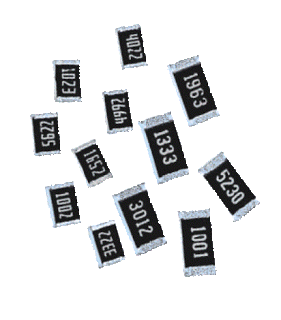
SMD resistors

The shape of the SMD resistor is rectangular.

There is a presence of a metallized area in the chip resistors at any one side of their body which in turn enables the contact of the printed circuit board with the chip resistor by using the solder.

A ceramic substrate is one of the components of the resistor and a metal oxide film is deposited over it. The resistance of the resistor is determined by the actual film’s length and thickness.

Since metal oxide is used to manufacture the SMD resistors which enable the resistor to be highly stable along with the tolerance level also being high. The element with which a ceramic substrate is made up of is high alumina ceramic.

The use of the high alumina ceramic in the SMD resistors provide stable insulation on the basis of the resistive metal oxide element on which the resistor is set down.

The terminations of the SMD resistors are also important.

The contact which the SMD resistor needs to make with the chip resistor’s resistive element needs to be reliable while at the same time it should provide solderability of very high levels.

Such high levels are achieved through the usage of the nickel based layer to make an internal connection. At the same time and outer layer which is tin based is used to make the outer connection thereby achieving solderability of very high levels.

Packages of SMD Resistors

There are variety of different packages in which the SMD (Surface mount resistors) come. The size in which the packages of the chip resistors come has decreased significantly because of the advancement of the technology over a period of time.

Specifications of SMD Resistors

There are a large number of companies which are involved in the manufacturing of the SMD resistors. The specifications of the SMD resistors thus vary based on the specifications provided by the manufacturer.

Thus, while deciding on the requirement of the SMD Resistors, one needs to check the rating of the manufacturer for the given SMD resistor. At the same time one can anticipate the rating at a general level.

Power Rating: Due consideration needs to be provided to the power rating in a given design.

The power levels of the designs which use the SMD resistors are of very smaller levels when compared to the circuit designs which use wire ended components.

Tolerance: The tolerance values of the Surface Mount Resistors which use the metal oxide film for their manufacturing is very close.

The tolerance levels which are available at a large scale include 1%, 5%, and 2%. Additionally, the values of the 0.1% and 0.5% can be achieved for the applications which are specialist applications.

Temperature Coefficient: The temperature coefficient values of the Surface Mount Resistors which use the metal oxide film for their manufacturing is very high.

The temperature coefficients levels which are available at a large scale include 100 ppm/C and 25,50 ppm/C.

Applications of SMD Resistors

There are a variety of designs for which the use of the surface mount resistors is done.

The size of the SMD resistors enables them to have various advantages such as: they can be used for the techniques of the automatic assembly; provide high performance at radio frequencies; and high suitability for the circuit boards which are compact in nature.

The capacitance and the inductance of the SMD resistor are spurious in nature because of their size. Thus, one needs to be careful while the power dissipation of the SMD resistors are calculated since the power levels which are dissipated is very low.

You'll also like:

  • 1.  IC 4018 Datasheet, Pinout Function Explained
  • 2.  BC547 Transistor Datasheet [45V, 100mA NPN Transistor]
  • 3.  IC 4070 Datasheet, Pinout Working, Truth Table, Electrical Characteristics
  • 4.  High Voltage Transistor MJ11021(PNP) MJ11022 (NPN) Datasheet – Complementary Pair
  • 5.  IRF640 Datasheet [200V, 18 Amp N-Channel MOSFET]
  • 6.  2N3906 Datasheet [40V, 200 mA, PNP Transistor]

About Swagatam

I am an electronics engineer with over 15 years of hands-on experience. I am passionate about inventing, designing electronic circuits and PCBs, and helping hobbyists bring their projects to life. That is why I founded homemade-circuits.com, a website where I share innovative circuit ideas and tutorials. Have a circuit related question? Leave a comment.... I guarantee a reply!

Previous Post: « Types of Switches, Working and Internal Details
Next Post: Obstacle Avoiding Robot Circuit without Microcontroller »

Reader Interactions

Comments

  1. Swagatam says

    May 14, 2016 at 1:38 pm

    I think a PCB designer will know much better than me, so you can consult a professional PCB designer for knowing more about this.

    Reply
  2. Swagatam says

    May 11, 2016 at 3:05 pm

    I am glad you could learn from this site…
    For power SMD devices I would recommend using a double sidedPCB with wide tinned copper area under the device over which the device is required to be soldered. the hind side of the PCB could be then suitably attached to a heatsink or an aluminum plate.

    Reply

Need Help? Please Leave a Comment! We value your input—Kindly keep it relevant to the above topic! Cancel reply

Your email address will not be published. Required fields are marked *

Primary Sidebar

Subscribe to New Circuit Ideas

Categories

  • Arduino Projects (87)
  • Audio and Amplifier Projects (132)
  • Automation Projects (17)
  • Automobile Electronics (101)
  • Battery Charger Circuits (83)
  • Datasheets and Components (104)
  • Electronics Theory (143)
  • Free Energy (37)
  • Games and Sports Projects (11)
  • Grid and 3-Phase (19)
  • Health related Projects (25)
  • Home Electrical Circuits (12)
  • Indicator Circuits (14)
  • Inverter Circuits (87)
  • Lamps and Lights (142)
  • Meters and Testers (69)
  • Mini Projects (46)
  • Motor Controller (64)
  • Oscillator Circuits (27)
  • Pets and Pests (15)
  • Power Supply Circuits (108)
  • Remote Control Circuits (50)
  • Security and Alarm (64)
  • Sensors and Detectors (101)
  • Solar Controller Circuits (59)
  • Temperature Controllers (42)
  • Timer and Delay Relay (49)
  • Transmitter Circuits (29)
  • Voltage Control and Protection (37)
  • Water Controller (36)

Calculators

  • Battery Back up Time Calculator
  • Capacitance Reactance Calculator
  • IC 555 Astable Calculator
  • IC 555 Monostable Calculator
  • Inductance Calculator
  • LC Resonance Calculator
  • LM317, LM338, LM396 Calculator
  • Ohm’s Law Calculator
  • Phase Angle Phase Shift Calculator
  • Power Factor (PF) Calculator
  • Reactance Calculator
  • Transistor Astable Calculator
  • Transistor base Resistor Calculator
  • Voltage Divider Calculator
  • Wire Current Calculator
  • Zener Diode Calculator
  • Filter Capacitor Calculator
  • Buck Converter Calculator
  • Boost Converter Calculator
  • Solar Panel, Inverter, Battery Calculator
  • Wire Current Calculator
  • SMPS Transformer Calculator
  • IC SG3525, SG3524 Calculator
  • Inverter LC Filter Calculator

People Also Search

555 Circuits | 741 Circuits | LM324 Circuits | LM338 Circuits | 4017 Circuits | Ultrasonic Projects | SMPS Projects | Christmas Projects | MOSFETs | Radio Circuits | Laser Circuits | PIR Projects |

Recent Comments

  • Swagatam on How Shunt Regulator TL431 Works, Datasheet, Application
  • Swagatam on Best 3 MPPT Solar Charge Controller Circuits for Efficient Battery Charging
  • SA on How Shunt Regulator TL431 Works, Datasheet, Application
  • Dan on Best 3 MPPT Solar Charge Controller Circuits for Efficient Battery Charging
  • Swagatam on Anti Spy RF Detector Circuit – Wireless Bug Detector

Company

  • Privacy Policy
  • Cookie Policy
  • About Me
  • Contact
  • Disclaimer
  • Copyright
  • Videos
  • Sitemap

Social Profiles

  • Twitter
  • YouTube
  • Instagram
  • Pinterest
  • My Facebook-Page
  • Quora
  • Stack Exchange
  • Linkedin
  • © 2025 · Swagatam Innovations