• Skip to main content
  • Skip to primary sidebar

Homemade Circuit Projects

Get free circuit help 24/7

New Projects | Privacy Policy | About us | Contact | Disclaimer | Copyright | Videos 

You are here: Home / Datasheets / IC 4070 Datasheet, Pinout Working, Truth Table, Electrical Characteristics

IC 4070 Datasheet, Pinout Working, Truth Table, Electrical Characteristics

Last Updated on March 4, 2023 by Swagatam Leave a Comment

The IC 4070 is a quad 2-input XOR gate IC which is designed for a wide range of digital logic applications. The XOR function is a logical operation that produces a high output (1) only when the inputs potentials are not similar. The IC 4070 contains four independent XOR gates in a single package which enables it to be a compact and cost-effective solution for designing digital circuits. The IC is compatible with both TTL and CMOS logic families and could be used with a wide voltage range. This makes it suitable for implementing in many different types of electronic devices.

Electrical Characteristics:

  • Supply voltage (Vcc): 3V to 18V
  • High-level input voltage (ViH): 2V to Vcc
  • Low-level input voltage (ViL): -0.5V to 0.5V
  • High-level output voltage (VoH): Vcc-0.1V
  • Low-level output voltage (VoL): 0.1V
  • Input leakage current (Ii): -0.1uA to 0.1uA
  • Output leakage current (Io): -0.1uA to 0.1uA
  • Propagation delay time (tpd): 50ns typical, 60ns maximum
  • Quiescent current (Iq): 4uA typical, 20uA maximum

Pinout:

The following diagram of the IC 4070 shows the pinout configuration of the IC in details:

caution electricity can be dangerous
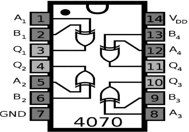
  • Pin 1: Input of Gate 1
  • Pin 2: Input of Gate 1
  • Pin 3: Output of Gate 1
  • Pin 4: Output of Gate 2
  • Pin 5: Input of Gate 2
  • Pin 6: Input of Gate 2
  • Pin 7: VSS, Ground or 0V Supply Input
  • Pin 8: Input of Gate 3
  • Pin 9: Input of Gate 3
  • Pin 10: Output of Gate 3
  • Pin 11: Output of Gate 4
  • Pin 12: Input of Gate 4
  • Pin 13: Input of Gate 4
  • Pin 14: VDD or the Supply positive input

Truth Table:

The IC 4070 consists of four XOR gates, each with two inputs (A and B) and one output (Y). The truth table for an XOR gate is as follows:

ABY
000
011
101
110

From the above we can easily understand the working of the IC 4070 pinouts. As we already know that the IC 4070 includes 4nos of 2 input Exclusive OR gates or XOR gates.

Each of these gates have two inputs and one output.

Depending on how the inputs are supplied with a positive of 0V supplies, the outputs produce a logic high or a logic low. Here,s logic high is always equal to the pin#14 VDD value, and the logic low is always 0V or equal to the pin#7 VSS value.

Let's take the example of the first gate which has two inputs terminating at pin#1 and pin#2, and an output terminating at pin#3.

Let's consider the two inputs as A and B, then referring to the above truth table we can see that when both the inputs are 0V, the output is also zero volts.

When the two inputs are different, meaning one is with positive voltage equal to VDD and the other one is 0V then the output is always a logic one or equal to VDD value.

When both the inputs are positive with value equal to VDD, the the output is always zero volts.

Applications:

The IC 4070 can be normally used for the following mentioned applications:

  • Digital logic circuits
  • Encoders and decoders
  • Adders and subtractors
  • Parity generators and checkers
  • Frequency dividers and multipliers
  • Data transmission and reception systems
  • Audio and video processing circuits
  • Voltage-controlled oscillators (VCOs)

You'll also like:

  • 1.  Half-Bridge Mosfet Driver IC IRS2153(1)D Datasheet
  • 2.  IC 4001 Datasheet, Pinout, Applications
  • 3.  IC 723 Voltage Regulator – Working, Application Circuit
  • 4.  LM35 Pinout, Datasheet, Application Circuit
  • 5.  IC 4033 Pinouts, Datasheet, Application
  • 6.  IC 4025 Datasheet, Pinout Working, Application

About Swagatam

I am an electronic engineer (dipIETE ), hobbyist, inventor, schematic/PCB designer, manufacturer. I am also the founder of the website: https://www.homemade-circuits.com/, where I love sharing my innovative circuit ideas and tutorials.
If you have any circuit related query, you may interact through comments, I'll be most happy to help!

Have Questions? Please Comment below to Solve your Queries! Comments must be Related to the above Topic!!

Subscribe
Notify of
0 Comments
Inline Feedbacks
View all comments

Primary Sidebar

Categories

  • 3-Phase Power (15)
  • 324 IC Circuits (19)
  • 4017 IC Circuits (52)
  • 4060 IC Circuits (26)
  • 555 IC Circuits (99)
  • 741 IC Circuits (20)
  • Arduino Engineering Projects (83)
  • Audio and Amplifier Projects (115)
  • Battery Chargers (83)
  • Car and Motorcycle (95)
  • Datasheets (74)
  • Decorative Lighting (Diwali, Christmas) (33)
  • Electronic Components (101)
  • Electronic Devices and Circuit Theory (36)
  • Electronics Tutorial (120)
  • Fish Aquarium (5)
  • Free Energy (34)
  • Fun Projects (13)
  • GSM Projects (9)
  • Health Related (20)
  • Heater Controllers (29)
  • Home Electrical Circuits (103)
  • How to Articles (20)
  • Incubator Related (6)
  • Industrial Electronics (28)
  • Infrared (IR) (40)
  • Inverter Circuits (98)
  • Laser Projects (12)
  • LED and Light Effect (93)
  • LM317/LM338 (21)
  • LM3915 IC (25)
  • Meters and Testers (66)
  • Mini Projects (149)
  • Motor Controller (67)
  • MPPT (7)
  • Oscillator Circuits (26)
  • PIR (Passive Infrared) (8)
  • Power Electronics (34)
  • Power Supply Circuits (79)
  • Radio Circuits (10)
  • Remote Control (48)
  • Security and Alarm (62)
  • Sensors and Detectors (121)
  • SG3525 IC (5)
  • Simple Circuits (75)
  • SMPS (29)
  • Solar Controllers (61)
  • Timer and Delay Relay (53)
  • TL494 IC (5)
  • Transformerless Power Supply (8)
  • Transmitter Circuits (41)
  • Ultrasonic Projects (16)
  • Water Level Controller (45)

Calculators

  • AWG to Millimeter Converter
  • Battery Back up Time Calculator
  • Capacitance Reactance Calculator
  • IC 555 Astable Calculator
  • IC 555 Monostable Calculator
  • Inductance Calculator
  • LC Resonance Calculator
  • LM317, LM338, LM396 Calculator
  • Ohm’s Law Calculator
  • Phase Angle Phase Shift Calculator
  • Power Factor (PF) Calculator
  • Reactance Calculator
  • Small Signal Transistor(BJT) and Diode Quick Datasheet
  • Transistor Astable Calculator
  • Transistor base Resistor Calculator
  • Voltage Divider Calculator
  • Wire Current Calculator
  • Zener Diode Calculator

© 2023 · Swagatam Innovations

wpDiscuz