In this post I have explained a simple obstacle avoiding robot circuit without microcontroller and without using special motor driver circuits or ICs. The idea was requested by Mr. Faiyyaz
The Design
Basically it's in the form of a moving vehicle which is able to detect and avoid potential obstacles on its path and change its direction appropriately so that its motion stays uninterrupted, simple!
The operation is thus automatic without any manual or human intervention.
The presented idea of an obstacle avoiding robot without microcontroller as the name suggests does not employ a microcontroller and therefore is extremely simple to build and suitable to any new hobbyist.
While designing the circuit I realized that in order to implement the principle at least a couple of obstacles sensor modules would be required, because using a single module can cause erratic movement of the motor and may not help a smooth diversion or turning of the vehicle towards a free path.
The vehicle motor set up is quite similar to the remote control toy car which I had discussed in one of the earlier posts.
The following diagram represents one of the modules of the system, and therefore two or a pair of such modules would be required across the right and the left sides of the vehicle.
The idea is simple and works without microcontroller and without special motor driver ICs. That means you can make it without any kind of coding and without using any kind of complex motor driver IC.....and the circuit allows you to use any DC motor regardless of its power, so even high power obstacle avoiding vehicles could be made using this circuit which are normally used in malls and similar retail outlets.
Circuit Diagram
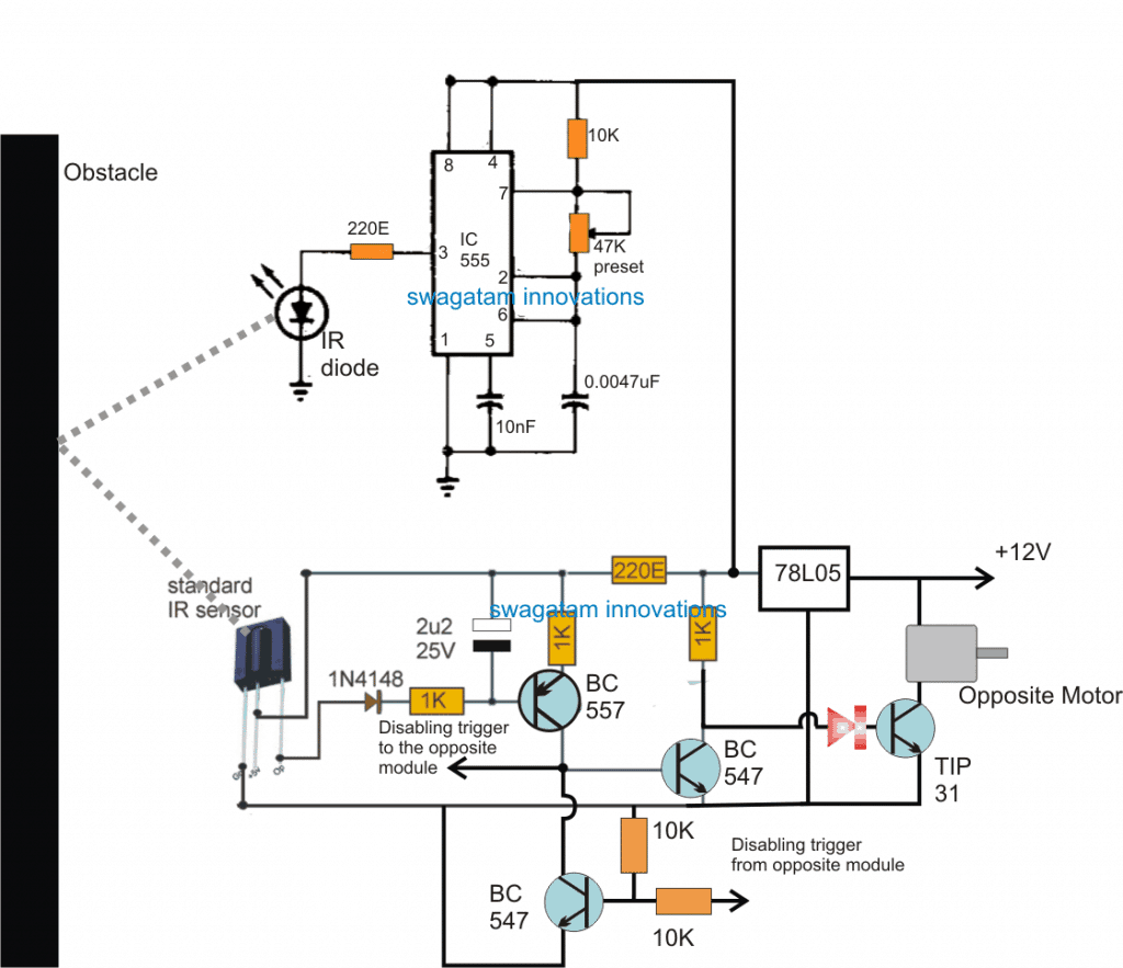
Now let's try to understand the above circuit with the help of the following explanation:
How it Works
The IC 555 is configured as an IR transmitter and is set to generate a constant 38kHz frequency, while the adjoining transistorized circuit is configured as the receiver stage or the IR sensor stage.
Let's assume it's the right side module, and suppose this module happens to be the first to detect an obstacle in the path.
Therefore as soon as an obstacle is detected, the 38kHz frequency generated by the 555 IC is reflected towards the sensor of the adjoining receiver circuit.
The receiver instantly activates the associated transistors such that the final driver transistor is inhibited from conducting.
Now the motor which is controlled by this transistor is supposed to be located on the left side of the vehicle, that is on the opposite side of this module...similarly the motor located on the right side is actually controlled by the left side module.
Consequently, when the above assumed right hand side obstacle detector module activates, it stops the left hand side motor, while the right side motor is allowed to move normally.
This situation results in the vehicle being forced to take a left side diversion...which means now the assumed left module starts getting even more stronger obstacle signals and keeps forcing the vehicle to proceed harder on the ongoing diversion until it has completely avoided the obstacle. The module now stops receiving the obstacle signals and the vehicle begins moving ahead normally on its new path.
While the above diversion is carried out the left side module is forced to become more and more isolated and away from the obstacle so that it does not get an opportunity to interfere in the procedure, and allow a clean and smooth diversion of the vehicle.
Exactly the same procedures are implemented in case the left side module happens to sense the obstacle ahead of the right side module, wherein the vehicle is forced to move harder and harder toward the right side.
We can also see a "disabling" circuit stage in the module which are interconnected across the left and the right side modules. This stage is purposely introduced to ensure that both the modules are never activated together.
Therefore for example if the left side module becomes the first to detect an obstacle, it immediately disables the right side module and initiates the diversion of the vehicle on the right and vice versa.
The sensor IC could be an standard TSOP17XX series
For more info regarding the above sensor IC you can learn how to connect TSOP1738 IC
And the motor should be equipped with gear boxes so that the movement is originally maintained at a controlled level.
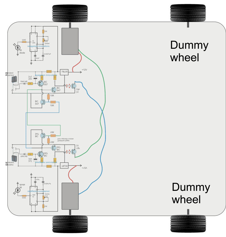
Wheel Set Up
The complete set up of the left and right module and the associated electrical connections can be witnessed in the figure below:
Update
A little thinking tells us that the above simple obstacle avoiding robot circuit could also be implemented by using a single module, instead of the two.
However a single module would allow the vehicle to carry out a single sided diversion every time it detects an obstacle, therefore the system could be configured either to take a clockwise diversion or anticlockwise diversion depending on which motor is connected with the circuit for the actions.
The example set up can be visualized in the following image:
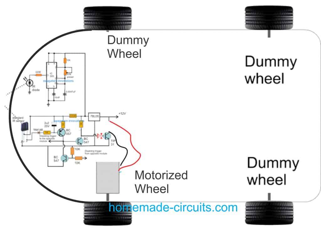
However, it seems there's one problem with the above single motor set up. If suppose the vehicle encounters a right angled corner on the left side. This will force the vehicle to keep moving anticlockwise, until it takes a U-turn, and begins moving back towards the same direction from where it had started. This is not something the user would appreciate.


Questions & Answers
Hello,
I may be confusing the wiring of the 78L05. If I am reading it right, Pin 1 is connected to 12v, via the 220ohm resistor, Pin 2 is connected to Ground, and Pin 3 is connected to the motor itself? I tried the circuit and it appears to be getting hot, so I just wanted to verify. Thank you in advance, I am a big fan of this sight!
Hello, I think you are connecting the input/output pins oppositely. The input pin must go to the +12V and the motor, the center pin to ground and the Output pin to the circuit.
Ah, misread the pinout, my bad. Thanks!
No problem!
Hello
The diode 1n4148 stops the voltage on base from running down to ground when the IR receiver gives out Low output. with the diode there the base on BC557 is stuck around 4,7V and keep the PNP transistor closed. However when I remove the diode the voltage from base gets dragged down and the transistor opens.
But without the diode this 4,7V will go to the output pin of the IR receiver.
is there any other way to go about this?
Thank you
Hi, you are right the 1N4148 polarity is incorrect, so you can just reverse the polarity of the 1N1418 diode and check the working of the circuit.
Hello Swagatam,
Do we need to fix IR diode or IR sensor in at some angle ? Or may be close to each other?
Thanks in advance
Hello Ritesh, yes some experimentation will be required for the Tx/Rx LEDs until the most effective reflection angle is achieved.
Hello Swagatam,
Do we need a paired IR Diode and IR sensor or we can choose any and make a combination?
Hi Ritesh, pairing is not required, but the IC 555 must be set to generate 38 kHz.
Hello Swagatam,
Thanks for your reply. Yes that is my question. Motor one wire is going to collector of TIP31 and second wire is goind to +12V?
The collector wire is the negative wire of the motor.
Hello Swagatam,
Normally motor has 2 wire connection. I can not see GND connection of motor. Do you have actual Schematic? It is bit difficult to understand where there is over wire.
Thanks
Hello Ritesh, the motor is a two wire motor, the TIP31 emitter line is actually the ground line of the circuit. I forgot to show the negative battery connection to this line.
Hello Swogatam,
thank you..So the motor has 3 wire. 12V, GND and to transistor(TIP31)?
Hello Swagatam,
Could you please suggest some IR diode which is connected LM555?
Hi Ritesh, any standard photodiode will work for the transmitter diode.
Thank you swagatam,
I will check it online.
Do you take small projects private or on contract basis. I have some small projects. I will pay according to the task.
Thank you Ritesh, sorry, I do not take external jobs due to work pressure.
Dear Swagatam,
First of all nice work and may god bless you.
Do you have similar application using microcontroller?
Thanks Ritesh, God bless you too.
Sorry, I do not have an Arduino version at this moment, but I think it is available online from other sources.
I am unfamiliar with these BJTs. What exactly is the purpose of all of these in this schematic? I was wondering if I could use MOSFETs.
To switch the motor in accordance with the IR signals, mosfets cannot be used
my obstacle avoiding car does not working, my motors and ir diode work properly but it can not detect obstacle
The 555 IR diode must be set at 38 kHz, otherwise the circuit will not work
Sir this red symbol before the transistor tip31 is diode or led ?
Simra, the red diode at the base of the TIP31 transistor is an LED (RED LED)
Hello again.
I am also not familiar with the designation “2u2” 25V component. What is this device?
Thanks again for your time.
Rick
Hello Rick, 2u2 refers to 2.2uF. It is an electrolytic capacitor
Swag,
Thanks for the quick response, and have a great day.
Rick
You are welcome Rick!
Hello Swagatam,
I enjoyed reading (and documenting) your article on the Obstacle Avoiding Robot. I am unfamiliar with the discrete component nomenclature “220E.” What is it? I have the other bits to build this project, and look forward to experimenting with it.
Thank you for your time,
Rick
Thank you Rick, Glad you liked the post, 220E refers to 220 Ohms resistor. Let me know if you have any more doubts, Ill be happy to help!
Greetings Swagatam – first thank you for your website, wonderful projects.
Regarding the frequency of this particular circuit. The equation for frequency is
1/f = T = t1+t2 = ln 2 * (R1 + 2*R2) * C
Therefore, with R1 = 10,000 ohm, R2 = 47,000 ohm, and C = 0.0047 uF = 4.7 nF = 4700 pF
the frequency is 3.0 kHz.
Changing C to 470 pF makes the frequency 30 kHz.
To get a frequency of 38 kHz requires C = 370 pF or changing the resistance, for example setting the preset to about 37,000 ohms with a 470 pF capacitor.
Would it also be reasonable to change the resistance to R1 = 1,000 ohm and R2 = 3,500 ohm with C = 4700 pF (which by the above equation gives a frequency of 38 kHz)?
Thank you for your time.
Hi Renato, You can either tweak the resistor or the capacitor or both, it won’t matter, you will anyhow get the required results successfully, however according to me the capacitor value used should be preferably be above pf range and below 1uF. I would recommended using a practical confirmation instead of depending on the formula.
Sir can I use 100k preset instead of 47k?
Thank you sir 🙂
yes you can
Can you please do circuit using 2 wheels dc and 1 free wheel on front (all direction)
the idea is very straightforward and I have explained it in the article…so there's nothing much to be explained further…
the capacitor are not critical, a ceramic will also work.
make sure the transmitter frequency is compatible with the TSOP device (38kHz)…or you can try the operations with a TV remote control.
to confirm the working of the transistors, you can manually ground the 1N4148 end momentarily….this should stop the motor for that moment. This will confirm that your circuit is OK, and only the sensor section needs to be confirmed.
I cannot get the connection because currently were testing the diagram on a breadboard. Were using ceramic as capacitor is it right? Our power is 9v is it enough ? Motor is running but sensor is not working. May I ask if were given a breadboard connection(actual pic) of this as a reference would be that okay. Thank you for replying my comment.
you can simply modify the wheel configuration in the given layout and convert it into a 3 wheel version
HI SWAGATAM how can you modify that circuit and add on a robotic voice circuit such that when an obstacle is detected a robotic voice is produced that obstacle is detected
Hi Davis it could be easily done by integrating a prerecorded voice module with the relevant relays of the circuit
Thanks sir I will try this circuit thank you so much
sure faiyyaz, thanks
Sir, can I use this gsm circuit as single motor control for water pump set ,plz sent to circuit sir
which gsm circuit?