The industry of electronic circuits uses resistors of various different types available in the market. The properties of these resistors vary and are different for each type being ruled by their manufacturing and construction process.
By: S. Prakash
Over a time period, the resistors of various types which were and are being used in the production of electronics have undergone continuous change.
The resistors which were used previously consisted of lead as their component along with being very large in size when compared to the resistors of the present day which resulted in low performance level of the former.
The current day resistors are comparatively smaller in size along with performing at a high level.
Resistors of variable and fixed types
The most major and basic category in which a resistor can be differentiated is on their nature of being either of variable or fixed type. The applications for which these resistors of different types are used differ respectively.
Fixed Resistors: The resistor which is used most widely in the industry is the fixed resistors. The electronic circuits use the fixed resistors for correcting and setting the right and appropriate conditions within their circuits.
The determination of the values of the resistors is carried out in the circuit’s design phase. These values are not required to be adjusted or changed in any manner with respect to the circuit.
The decision as to which resistor type needs to be used is dependent on the various circumstances in which they are to be used. These resistor types have been described in further detail in the subsequent sections.
Variable Resistors: The variable resistors consist of two elements, namely a fixed resistor element. The main element of the resistor is tapped onto by the slider present in the resistor.
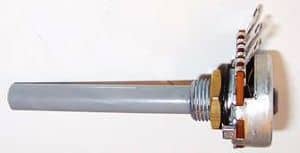
Thus, this provides the resistor’s components with three connections. Out of these three connections, the fixed element is fixed to the two connections while the slider is the third connection.
Thus, this enables the components to act as an agent of the variable potential divider.
This also required that they use the three connections altogether. The variable resistance can be provided to the resistor by connecting the one end of the resistor with the slider.
Potentiometers, presets and rheostats are some of the common examples of variables resistors
Resistors of Fixed Types
The various different fixed resistor types are as follows:
Carbon composition: The carbon composition resistors were very common previously but the currently their usage has decreased considerably.
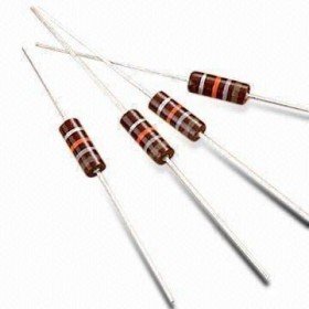
The carbon resistors are manufactured by mixing the granules of the carbon with an element which acts as a binder and this mixture in turn is made in the shape of small rods.
The carbon resistors had a disadvantage in terms of suffering from a very high negative temperature coefficient.
This is due to their comparatively large size when viewed from the current day standards.
The carbon composition resistors also suffered another downfall wherein due to aging of the resistor with time or an exposure to excessive heat, the carbon composition resistor goes through irreversible changes which are erratic and large.
Additionally, a large amount of noise is generated in the carbon composition resistor when the current flows through it because of the carbon’s granular nature and its association with the binder.
Carbon Film (CFR 5%): The carbon film resistor is manufactured by the induction of the process of a hydrocarbon’s cracking into a former made up of ceramic.
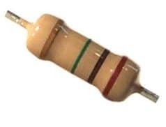
The resistance of the film which is deposited as a result of the above process is set by making a cut into the film in the shape of helix. This has resulted in very high inductance in the carbon film resistors and thus most of the RF applications cannot use it much.
A -900 ppm/ºC to -100 ppm/ºC of temperature coefficient is exhibited by the carbon film resistors. A ceramic tube or a conformal epoxy coating is used to protect the carbon film.
Metal Oxide Film (MFR 1%): The metal oxide film resistor has come to become the resistor which is used in the current day industry at a wide scale along with another resistor type of the metal film type.
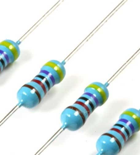
The metal oxide film resistor type uses a film of metal oxide instead of a carbon film to be deposited on the ceramic rod.
The deposition of the metal oxide which can be found on the ceramic rod can include tin oxide. There are two ways in which the component’s resistance is adjusted.
Firstly, at the initial stages of the manufacturing process, the deposited layer’s thickness is controlled. Thereafter the adjustment is done in more accurate way by cutting a grove in the shape of helical form in the film.
Again, as in the previous case, the conformal epoxy coating is heavily coated on the film to protect it.
The ±15 ppm/ºK of temperature coefficient has been observed in the metal oxide film resistor which results in a very high and superior function of this resistor when compared to any other resistor which is carbon based.
Additionally, the tolerance levels to which these resistors are supplied are very close including the standard tolerance levels of ±2%, ±1%, and ±5% being available.
Also, when compared with the resistors which are carbon based, there is very low exhibition of noise in these resistors.
Metal Film: There is a great similarity which can be observed between the metal oxide film resistor and the metal film resistors in terms of their performance and appearance.
A metal film is used by this resistor in place of the metal oxide film which is used in the metal oxide film resistor. The metal film which is used in the resistor can include nickel alloy.
Wire Wound: The applications which require very high power in general use this type of resistor. A wire is wounded around a former in order to manufacture this type of resistors.
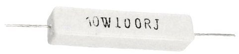
The resistance of these wires is higher than that of the normal resistance. The varieties of these resistors which are expensive consist of the wire which is wound on a former made up of ceramic along with a cover of the silicone or citreous enamel over it.
The temperature coefficient of these resistors is very low along with a reliability of very high level being exhibited by these resistors when exposed to high power which enables it to operate at high performance level.
But these properties are also dominated by various other factors such as type of the wire being used, type of former being used, and more.
Thin Film: The majority of the resistors which are of surface mount types use the technology of the thin film. The resistors based on this technology are used widely in the current day industry where the number goes up to billions here.
Non-Leaded and Leaded types of Resistors
The manner in which the components or the resistors are connected acts as an important determinant of the differentiation of the components and the resistors.
The manner in which the components were connected previously has changed over the time majorly due to the use of the techniques of mass production and the circuit boards being used at a widespread level.
This is especially true for the components which the mass production process incorporates.
On the basis of the method of connection, the two major categories of the resistors are as follows:
Leaded Resistors: Since the times when the electronic components had first come into use, the leaded resistors had also come into use since those times.
The lead which came from the element of the resistor were required wherein the components were required to be connected in various different forms to the terminal posts.
Their usage has not stopped till date and only technique has changed wherein in the current practices where there is more use of the printed circuit boards, the holes present in the boards are used to insert the lead and then the reverse side is used to solder it where one can find the tracks.
Surface Mount Resistors: The since the time when the technology of the surface mount have been introduced, there has been a significant increase in the surface mount resistors.
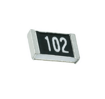
The technology which is used to manufacture the surface mount resistor is the thin film technology. Through this technology, the resistor can obtain the values in full range.

Questions & Answers
sir ,if i want to use 2m2 resistor instead of this can i use TWO RESISTOR OF 1M AND ONE RESISTOR OF 2K AND THAT SHOULD BE CONNECTED IN PARALLEL OR ANY EASY METHOD . THANK YOU
Thank you sir
manjunath, for an accurate equivalent you can use two 1M resistors and one 200K resistor, all in series. otherwise just two 1M will also work for a 2M2 replacement in most cases, except timer application