This simple 20 watt home tube light circuit will work with any 12V battery and uses very few components yet is able to produce a reasonable amount of white light.
The components used are very common and can be easily procured from the local electronic retailer.
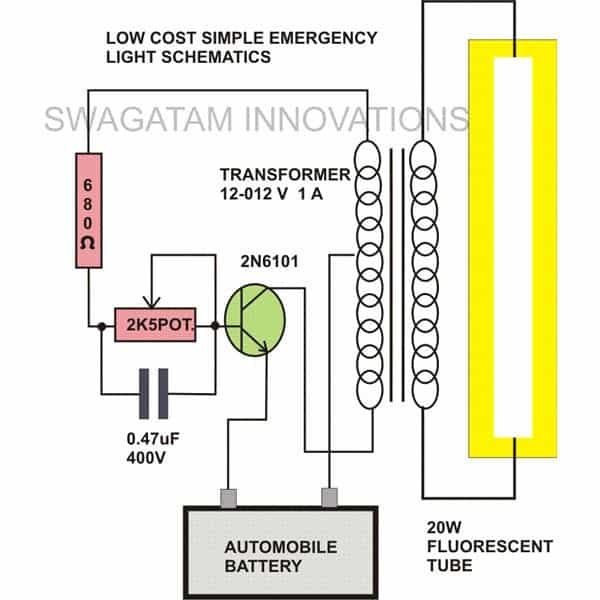
The idea is simple, the secondary winding of Tr1 and T1 along with the associated components forms a high frequency oscillator circuit.
How the Circuits Works
This oscillations forces an AC in the secondary winding of the transformer which is further induced into the primary of the transformer and stepped up to the corresponding rated value ofthe transformer.
The transformer used is an ordinary 12-0-12 volt 1Amp rated, it can be retrieved from any old, junk power supply unit that might be lying in your electronic junk box.
The transistor also is an ordinary type, here a 2N6101 is shown, but any other similar type will do. You may try a 2N3055 transistor or even a D1351 in place of the specified one.
The 2k5 preset is used for adjusting the frequency of the circuit which in turn affects the brightness of the connected tube.
The preset must be carefully optimized for obtaining maximum brightness on the tube and yet keeping the consumption on the relatively lower side.
The 0.47uF capacitor is also introduced for enhancing the output from the tube light, you may other nearby values for improving the overall brightness.
The battery can be a 12V, 7 AH battery which should last many hours.
However you cannot expect full striking brightness from this circuit. When I tested this circuit, I could never bring the tube light to its actual specified striking brightness.
The following diagram shows how to make a simple 20 watt fluorescent tube, 12V converter circuit.
Circuit Diagram Diagram
Detailed Working Description
Transistor Switching:
So we have got the 2N3055 transistor in an astable multivibrator setup which basically means it is a self-oscillating circuit which switches itself on and off. Here is how it works:
The base of the 2N3055 connects to one of the outer terminals of the 12V transformer winding. This happens through a potentiometer (2.5kΩ) and a 680Ω resistor. When we turn the circuit on, the potentiometer controls the voltage going to the transistor base, which in turn controls how much current flows into it.
Once the voltage at the base reaches about 0.7V, the transistor starts to conduct, meaning it lets current flow. This current comes from the transformer’s 12V side and flows through the transistor (from the collector to the ground or -12V). This creates a voltage drop across the transformer’s primary winding which causes current to flow through the secondary side, generating an AC voltage and stepping it up.
Oscillation Mechanism:
Because the center tap of the transformer is connected to the positive terminal of the 12V battery, and the transistor’s emitter connects to the negative terminal. This creates a feedback loop, which is what keeps the circuit oscillating.
When the transistor turns on, the current flowing through the transformer primary winding creates a magnetic field which then causes the transformer to turn off.
Once the transformer de-energizes, it forces the transistor to turn back on, and the cycle continues.
That feedback through the transformer windings and the transistors base-emitter junction keeps everything running in a loop, making the circuit oscillate on its own.
How the 12V is Stepped Up to 220V:
The transformer is what steps up the 12V to 220V. It has two sides, the primary side which is connected to the transistor and the battery and the secondary side which is where the fluorescent lamp connects.
The 12V AC from the primary side of the transformer gets boosted to 220V AC on the secondary side. The reason this happens is because of the transformer turns ratio. If the transformer is designed to step up from 12V to 220V, its turns ratio is about 18.33. This means for every 1 turn on the primary there are about 18.33 turns on the secondary which boosts the voltage from 12V to 220V.
Frequency of Oscillation:
The frequency at which the circuit oscillates depends on a few factors, like how fast the transistor can switch and the inductance of the transformer. Since the transistor is basically flipping on and off, the frequency is controlled by:
The resistor and potentiometer at the base which determine how fast the transistor switches.
The inductance of the transformer which also affects the switching speed.
The 2N3055 characteristics, like its response time and switching speed.
Normally the oscillation frequency comes in the range of 20 kHz to 50 kHz. This high frequency makes sure that the energy is transferred efficiently to the transformer. This range is also ideal because the transformers core works best at these frequencies and it reduces the losses compared to lower frequencies.
Estimating the Frequency:
The exact frequency can vary depending on the things like the potentiometer value, the transformer’s design and the transistor’s characteristics. But in most cases you will find that the frequency will be in the range of 20 kHz to 50 kHz which is common for small power supply circuits.
Calculations:
Oscillation Frequency (fosc):
The frequency of oscillation is determined by the characteristics of the transistor or the BJT and the transformer. A typical formula for the oscillation frequency in a circuit like this can be estimated by considering the time constant of the base circuit, the transistor switching characteristics, and the transformer inductance.
However a basic approach to estimating the oscillation frequency is based on the switching speed of the transistor and the transformer inductance:
fosc ≈ 1 / (Lprimary * Rbase)
Where:
- fosc = Frequency of oscillation (Hz)
- Lprimary = Primary inductance of the transformer (H)
- Rbase = Base resistance (the combination of the potentiometer and the 680Ω resistor in series)
Since the exact inductance value for the transformer is not provided, so estimating the frequency usually will depend on empirical values, with oscillation frequencies which may typically ranging from 20 kHz to 50 kHz for such circuits.
Turns Ratio of the Transformer:
The turns ratio of the transformer decides how the input 12V AC is stepped up to 220V AC for the lamp:
Turns ratio = Vsecondary / Vprimary
Where:
- Vsecondary = Voltage on the secondary side of the transformer (220V AC)
- Vprimary = Voltage on the primary side of the transformer (12V AC)
For a 12V to 220V step-up, the turns ratio is approximately as given below:
Turns ratio = 220 / 12 ≈ 18.33
This means that for every 1 turn on the primary side we have 18.33 turns on the secondary side of the transformer.
Base Current (IB):
The base current is controlled by the potentiometer and the 680Ω resistor. The base current can be calculated using Ohm's law:
IB = (Vbase - VBE) / Rbase
Where:
- IB = Base current (A)
- Vbase = Voltage at the base of the transistor (depends on the potentiometer setting)
- VBE = Base-emitter voltage of the transistor (typically 0.7V for 2N3055)
- Rbase = Total base resistance (sum of the 2.5kΩ potentiometer and 680Ω resistor)
The base current controls the collector current in the transistor.
Collector Current (IC):
The collector current depends on the base current and the current gain (β) of the transistor:
IC = β * IB
Where:
- IC = Collector current (A)
- β = Current gain (also called hFE) of the transistor (typically between 20 and 60 for 2N3055)
- IB = Base current (A)
Power Dissipation in the Transistor (P):
The power dissipated by the transistor is calculated as shown below:
P = VCE * IC
Where:
- P = Power dissipated by the transistor (W)
- VCE = Collector-emitter voltage (V)
- IC = Collector current (A)
Transformer Primary Power (Pprimary):
The power drawn from the battery by the transformer can be approximately calculated through the following formula (assuming ideal conditions, with no losses):
Pprimary = Vprimary * Iprimary
Where:
- Pprimary = Power consumed by the transformer (W)
- Vprimary = Primary voltage of the transformer (12V AC)
- Iprimary = Current in the primary winding of the transformer (A)
The power which is delivered to the lamp will be approximately equal to the power consumed by the transformer, if we assume the ideal conditions.
Power Delivered to the Fluorescent Lamp (Plamp):
Assuming an ideal transformer, the power delivered to the fluorescent lamp will be as folows:
Plamp = Vsecondary * Isecondary
Where:
- Plamp = Power delivered to the lamp (W)
- Vsecondary = Voltage on the secondary side of the transformer (220V AC)
- Isecondary = Current on the secondary side of the transformer (A)
The current in the secondary can be calculated from the primary side using the turns ratio:
Isecondary = Iprimary / Turns ratio
Where:
- Iprimary = Current on the primary side of the transformer (A)
- Isecondary = Current on the secondary side of the transformer (A)
- Turns ratio = 18.33
Parts List
- Resistors are 1/4 watt 5% CFR
- 680 Ω = 1
- Potentiometer 2.5 kΩ = 1
- PPC Capacitor 0.47 µF / 50 V = 1
- Transistor 2N6101 or any equivalent = 1
- Transformer 12-0-12 V / 1 A = 1
- Fluorescent Tube Light 20 Watt = 1
- Battery 12 V / 7 Ah = 1


Questions & Answers
Please I need an autocutoff battery charging circuit diagram that will charge 6v 4.5a battery for powering rechargeable lamp(not automatic but manually operated) which will not be draining battery when fully charged. I want to use it to build rechargeable led lamp. again how can I make my light to continue with full brightness for every long time like the commercial products from lontor.
You can try applying the following simple design
Thanks a lot for the simple and precise schematic diagram. Please how can I make brightness of the lamps last very long like the commercial alternatives. For instance Lontor rechargeable lamps that use 6v, 4.5ah lasts for more than 8hours with full brightness. I connected 20pieces of 5mm hi-efficiency white led of 20ma current and forward voltage of 3.6. in parallel.
Moses, Did you connect a resistor in series with each LED? If your LEDs are 3.3V and the supply source is 6V then either the LEDs will burn or they will consume huge amount of current.
So please connect a series resistor with each LED. The formula for calculating the resistor value is given below:
R = supply voltage – LED voltage / LED current.
connect the above resistor in series with each LED and then connect all the strings in parallel.
hi swag , can I use higher value of resistor in the place of 680 ohm. if yes how much will be maximum
Hi kulothungan, 1k is the maximum you should use.
Hi Sir, what is the wattage of the resistor? what other value can i use?
also the preset can i use 5k pot? also the polarity of the battery where to connect the positive (+ )?
Hi Amor, the resistor is 1/4 watt, yes 5K or 10K will also do for the preset. Positive of the battery will connect with the center tap of the transformer!
Hi Sir Swag, does a heatsink needed for the transistor 2n3055?
the fluorescent tube in my place has two pins in each side. thanks
Hi Amor, yes it is needed. You can short those pins or simply use anyone of them on each side….
Good evening sir!
can we get 40 watt flour.light by fitting two of these inverter circuit?if yes how to connect it each other?
you can do it simply by using a higher rated transformer, no need of two units.
but the illumination will be always half due to a half wave conduction in the trafo
Hi friend,
Thanks again for this circuit.
I want circuit so it will run 18w tube(2ft tube) with the power of 3v 2A or 6v 2A battery, i have small transformer 6-0-6 500ma , but i dont want to use big one..(like if 1A transformer bigger then 500ma), if any changes i can make from your above circuit so please tell me, or which parts i have to replace??? i will replace the parts from the circuit you showing above.
Thanks in advance….
Hi Kamlesh,
the above shown circuit is not very efficient and will not illuminate the tube with full brightness….you can try the following instead:
https://www.homemade-circuits.com/2014/11/12v-car-laptop-charger-circuit-using.html
Is preset necessary for this circuit?
it's for adjusting the brightness of the tube to the optimal point
what is preset??
variable resistor
sir,will this inverter charge the battery??
sir,will this inverter charge the battery?
No, it won't
no, i think it won't work with a mosfet