In this post I have explained a few circuit diagrams for building AC motor speed controller circuits using back EMF concept.
Working Principle of AC Motors
So now, all those home type appliances like electric drill machines, sander machines, sewing machines, food mixer machines, etc. they all are mostly using that AC motor which is called series-wound type motor, right?
Then, when this motor starts working, then it creates something called back-electromotive force or just back-emf. That back-emf always goes up or down depending on how fast that motor is rotating. So if speed is more then back-emf also becomes more and if speed is less, then back-emf also becomes less.
Now the actual voltage which really goes inside that motor and runs it, that is not full supply voltage. It becomes supply voltage minus back-emf. So whatever is remaining after subtracting back-emf, that only goes to run the motor.
This thing is very interesting because this back-emf thing makes the motor kind of self-controlling type. We do not need any extra circuit or sensor for controlling the speed. It adjusts automatically.
Like suppose motor is doing some work and suddenly load becomes more then speed will drop, right? But when speed drops then back-emf also becomes less. So because back-emf got reduced, now more voltage enters the motor. That extra voltage helps to push the speed back to original level.
So in this way, motor always tries to keep its speed more or less stable by itself without any extra controller or feedback system.
Using Triac
Now most of the AC motors which we normally use, they are usually designed in such a way that they can run with only one fixed speed. They do not have any built-in speed variation feature.
But if we want to make their speed variable then we can easily use one simple method. That method is using Triac based phase-control circuit.
One good example of this kind of circuit is shown in the below figure. This type of circuit becomes very useful mainly for handling light load appliances like food mixer machines and sewing machines. For such light duty loads, this Triac circuit works very nicely for changing the motor speed as we want.
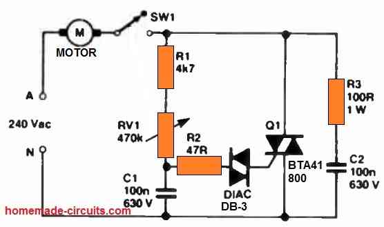
But still, it is important to understand one thing, that this type of Triac speed control setup has one small limitation. The speed control range is not very wide. It can control the speed, but only within a limited range.
Now if we compare with some other heavy duty appliances like electric drill machines and sanding machines then situation becomes different.
These machines face heavy changes in their load while working. Load keeps increasing and decreasing too much. Because of this they do not work well with the above simple AC motor speed controller circuit. That circuit cannot handle such big load fluctuations properly.
Using SCR
So for these kinds of high-load appliances, a better and more reliable option is to use an AC variable speed regulator circuit which works using SCR instead of Triac. One such good circuit is shown in the following diagram. This type of circuit can manage high loads and still control the speed nicely.
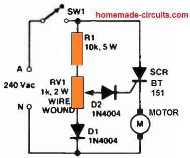
So now in this type of circuit setup, we are using one SCR as the main control device. This SCR gives half-wave power to the motor which means only one half cycle of the AC goes to the motor. Because of this, the motor speed and power both drop down a little, around 20 percent reduction happens.
Then during those off half-cycles where the SCR is not conducting, that time it quietly checks or senses the back-emf coming from the motor.
This back-emf information helps the circuit to automatically adjust the next gate triggering pulse for the SCR. That way the circuit tries to maintain some level of automatic speed control depending on how the motor is behaving.
Now there is one more important part. The small network made using R1, RV1, and D1, this thing is designed for adjusting the phase angle up to 90 degrees.
This phase control makes sure that every power pulse going to the motor is always minimum 90 degrees long. Because of this, the motor is able to get strong torque even during lower speed operations.
Then when the speed becomes low, this circuit behaves in a different way. It enters one special mode which we can call skip-cycling mode. In this mode, the circuit gives power pulses to the motor only sometimes, not in every cycle.
This skipping action helps to match the power delivery with the motor's actual load requirement.
Delivering High Torque
So this kind of AC motor speed controller circuit is very good in giving high torque even at lower speeds. That is one big advantage. But still there is one small issue. Sometimes the motor may show some light stuttering or vibration, especially at low speeds.
Same like the earlier circuit, here also we must understand that this system also has one limitation. The speed control range is not very wide. It works nicely but within a limited area of speed adjustment.
Closed Loop AC Motor Speed Controller using Back EMF
The next article presented below explains a very simple closed loop AC motor speed controller circuit that may be used for controlling single phase AC motor speeds.
The circuit is very cheap and uses ordinary electronic components for the required implementations.
The main feature of the circuit is that it’s a closed loop type, that means the speed or the torque of the motor can never get affected by the load or the speed of the motor in this circuit, on the contrary the torque is indirectly proportional to the magnitude of the speed.
Circuit Operation:
Referring the circuit diagram of the proposed single phase closed loop AC motor controller, the involved operations may be understood through the following points:
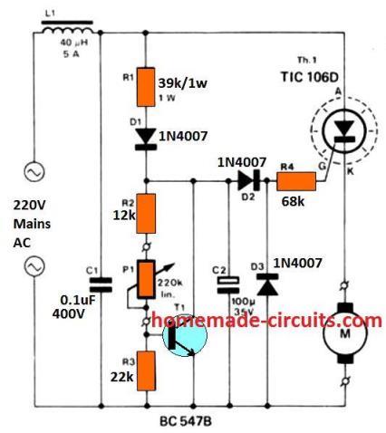
For the positive half cycles of the input AC, the capacitor C2 is charged through the resistor R1 and the diode D1.
The charging of C2 persists until the voltage across this capacitor becomes equivalent to the simulating zener voltage of the configuration.
The circuit wired around transistor T1 effectively simulates the operation of a zener diode.
The inclusion of the pot P1 makes it possible to adjust the voltage of this “zener diode”. Precisely speaking, the voltage developed across T1 is literally determined by the ratio between resistors R3 and R2 + P1.
The voltage across the resistor R4 is always maintained equal to the 0.6 volts that’s equal to the required conducting voltage of T1’s base emitter voltage.
Therefore it means that the above explained zener voltage should be equal to the value that may be acquired by solving the expression:
(P1 + R2 + R3 / R3) × 0.6
Parts List for the above closed loop AC motor speed controller circuit
- R1 = 39K,
- R2 = 12K,
- R3 = 22K,
- R4 = 68K,
- P1 = 220K,
- All diodes = 1N4007,
- C1 = 0.1/400V,
- C2 = 100uF/35V,
- T1 = BC547B,
- SCR = C106
- L1 = 30 turns of 25 SWG wire over a 3mm ferrite rod or 40 uH/5 watt
How the Load is Positioned for a Special Reason
A careful investigation reveals that the motor or the load is not introduced at the usual position; rather it’s wired up just after the SCR, at its cathode.
This causes an interesting feature to be introduced with this circuit.
The above special position of the motor within the circuit makes the firing time of the SCR dependant on the potential difference between the back EMF of the motor and the “zener voltage” of the circuit.
That simply means that the more the motor is loaded, the quicker the SCR fires.
The procedure quite simulate a closed loop type of functioning where the feedback s received in the form of back EMF generated by the motor itself.
However the circuit is associated with a slight drawback. The adoption of an SCR means the circuit can handle only 180 degrees of phase control and the motor cannot be controlled throughout the speed range but only for 50% of it.
Another disadvantage associated due to the inexpensive nature of the circuit is that the motor tends to produce hiccups at lower speeds, however as the speed is increased this issue completely disappears.
The Function of L1 and C1
L1 and C1 are included for checking the high frequency RFs generated due to the rapid phase chopping by the SCR.
Need less to say the device (SCR) must be mounted on a suitable heatsink for optimal results.
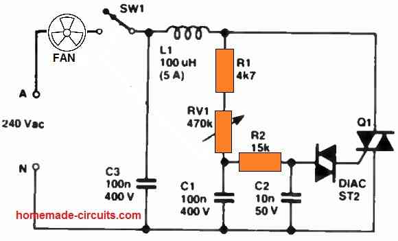
Back EMF Drill Speed Controller Circuit
This circuit is mainly used to control the steady speed of smaller series wound motors, as found in several electric hand drills, etc.
The torque and the speed is controlled by P1 potentiometer. This potentiometer configuration specifies how minutely the triac could be triggered.
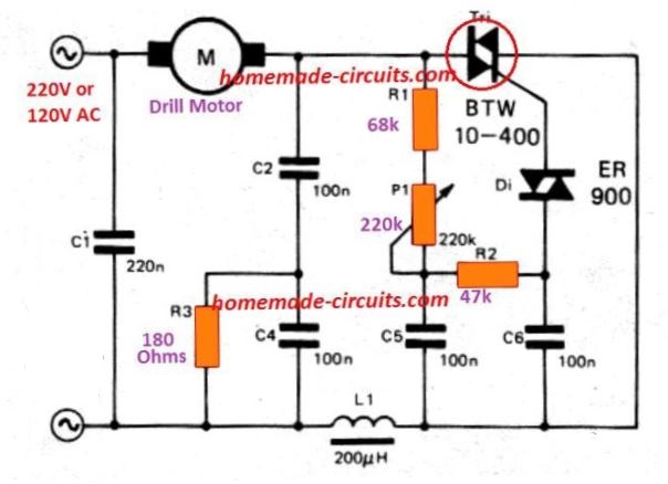
When the speed of the motor drops just under the preset value (with load connected), then the motor 's back EMF decreases.
As a result, voltage around through R1, P1, and C5 rises so that the triac is activated earlier and motor speed tends to increase. A certain proportion of speed stability is achieved in this manner.


Questions & Answers
I collected the diagram with a kontroler on the speed of a closed loop variable engine using reverse electric power but does not leave. I checked and measured all the elements several times and it didn’t work. I’m trying to adjust the speed you are an electric motor brush from a washing machine. Is the mistake in me?
What voltage do you get across the motor while adjusting the pot?
I use the Tiresior CT 784, probably from there comes the problem
Yes, I could not find any information about CT784, it seems it is not a transistor…
Няма напрежение
Hi Swagatam, can any of these circuits be used for a capacity start motor, 3/4 hp?
Hi Alan, yes they can be used for capacitor start type motors…
Thanks very much. Alan
Hi, that design looks like a standard fan dimmer circuit to me. I am not sure how it can work with a back EMF concept?
You are right, the 68k looks too high, you can probably reduce it to 10k or 15k and check the results.
A similar tested design has been discussed in the following post, you can check it out:
https://www.homemade-circuits.com/simple-ceiling-fan-regulator-circuit/
Последняя схема, на симисторе, у меня не заработала.
please try the following design and let me know:
Make sure to add a 47 ohm resistor in series with the diac to safeguard it from surge currents.
What role does C6 play in the firing time of the TRIAC
It converts each single firing pulse for the diac/triac into small bursts of pulses.
Buna ziua domnule.in locul lui p1 se poate pune un termistor pentru a lucra în funcție de temperatura?Când e rece motorul să meargă aproape cu viteza maxima,iar la căldură să se reducă turația.Multumesc.
Hi Gelu,
P1 can be replaced with an appropriately rated thermistor but it might not control the motor with full range, because a pot can be varied from zero to max, which might not be achievable with a thermistor.
Buna ziua domnule.Multu.esc mult pentru răspuns,chiar daca nu se oprește total motorul nu e o problema,am vrut doar să știu dacă merge un termistor in locul lui p1,ca sa nu fac degeaba circuitul.Fiti binecuvântat.
No problem Gelu, yes P1 can be replaced with a thermistor, if accuracy is not important.
However, please be warned that the last two circuits were not tested by me, they were contributed by external authors.
îmi asum riscul și dacă sunt probleme vă anunț.Multumesc.
Sure, if you face any problems please feel free to ask me here!
thanks
Bonjour, que faudrait -il faire pour un controle du moteur en surintensité afin de couper le triacs fonction que l’on trouve dans les verins de portails? MERCI
Dear I
try to install vfd for motors of neither small workshop at home
1.5 kw motors approx, electric
saw etc I use diac and triac bt139 800, but my question is with the harmonics
The reason is that my workshop is at the back of my house and the start-ups are strong because of the house lines
I have two sets of diac / triac, and I cannot find filters for these applications, I
would put a resistor and capacitor in parallel to the load in each case.
What value do you recommend? Voltage
220 volts at 50 Hz
Norberto
Hello, you can add a RC snubber, across the triac, but I think a snubber across a triac is required for protecting the triac from high voltage spikes, it is mostly not for harmonics. For harmonics you can try adding a 1uF/400V capacitor right across the motor wires and see if that helps
Sir, how could I simulate this circuit? I mean what software should I use?
you can use use proteus
Ibrahim, I never use simulator for my circuits, so can’t help much with this subject
Avrei un problema da risolvere
e’ possibile avere un circuito di protezione da cortocircuito e limitatore di potenza
su un alimentatore variabile da 300V DC.
Grazie per il VS aiuto
Gabriele
Hello Friend! Does this project work on a 1.4 hp 90v engine?
Hello friend, it will work if the motor is a series wound motor…
The resistor values in the parts list don’t match the circuit diagram.
I have corrected the parts list now so that they match with the diagram.
The diagram says voltage controlled by “P1, R3 and R4” Should this not be P1, R3 and R2 as these are the inputs to the base of the transistor?
R4 is the current limiter for the the Triac.
You are right, thank you for pointing out the mistake, I have corrected it now in the article.
I used a triac based dimmer to control ac 220v fan speed but motor creates hum noise in low speed. Is there any other circuit to control speed without hum noise?
use inductor capacitor filter as shown in the last diagrams of this article:
https://www.homemade-circuits.com/how-to-make-simplest-triac-flasher/
Can this circuit be used with a capacitor start motor?
Yes it can be tried…
Hi
does this cirquit work with 220v or is designed for 110v thanks
Hi, it can be used for both 220V and 120V inputs
What maximum power of the motor it can control and what components should be used for the speed controller for motor 1000 – 1200 watt, 115 v,
upto 300 watts can be controlled with the shown set up, for higher wattage you may have to upgrade the SCR with a higher value, and also reduce the gate resistor value appropriately
Does it control motor speed precisely without a use of tachogenerator?
Do you have the inductance value of L1? May i use a toroidal inductor instead?
By the way, amazing blog you have, and i really appreciate that you answer!
L1/C1 are not crucial, they are placed for PFC….to reduce RF interference in the atmosphere.
still if you want to include them , you can try 200 turns of 24 SWG magnet wire on any iron core such as an iron bolt.
I am glad you liked my website…please keep reading.
Will this circuit provide a stable frequency of revolution (RPM) even under load?
Meaning the motor will keep spinning at the same speed even when a load is aplied?
The design was originally intended to control drill machines, so probably any similar motor can be controlled with this circuit, although the capability is restricted to 180 degrees only….The resistors can be all 1/4 watt rated, a 10amp SCR will do if the motor max consumption does not exceed this value.
Thanks!
Im thinking to use it to control a washing machine universal motor in order to make a belt sander.
Will a 10amp thyristor be enought?
Also, what power dissipation capability will be needed in the resistors?
yes it will as long as long as the input voltage does not fluctuate….
Sir , How AC supply to motor is completed? Means Both the half cycles. My another Q is can I connect Transfomer pri to control 230 ac v , so that sec volage automaticaly get controlled. Sir Expecting your reply. my email vijayraopathak@yahoo.co.in
Thanks, & Regards,
Pathak, the above circuit will control only one half cycles of the AC and therefore will be able to provide a 180 degree phase control only….for full control you can make any regular dimmer switch circuit….the transformer can be also controlled by using a dimmer switch circuit in by connecting it series with the trafo primary