In this post we present 3 circuit ideas for creating beautiful Christmas tree light decorations. The first idea explains a transistorized flashing blinking LED string light which can be mounted on a Christmas tree.
The second circuit diagram describes an LED light effect generator which can be also installed over a real Christmas tree for decorating it with glittering LED lights.
The third circuit uses IC 4060 for generating random light effect using many different colored LEDs. At end of the post we also learn an 8 function Christmas tree light circuit, which is a bonus.
1) Using Transistors
The first circuit design is based on a simple transistors astable configuration which can create an attractive wig-wag flashing of the LEDs connected in strings.
These LED strings can be laid down on a Christmas tree for creating beautiful switching colorful LEDs which will flash and blink ON/OFF continuously.
The simple circuit diagram of the transistor astable can be witnessed in the following image:

Parts List:
- Resistors 47K 1/4 watt = 2nos
- Transistors BC547 or 2N2222 = 2nos
- Capacitors 10uF/25V = 2nos
In the above circuit diagram we can see pairs of transistors, capacitors, resistors cross coupled with each other to form the LED flasher network.
The circuit is designed to alternately flash two strings of LEDs connected across each of the points marked as "To LEDs"
The circuit diagram of the LED strings which needs to be configured across the indicated points can be seen in the following figure:

Parts List:
- All resistors are 330 ohms 1/4 watt = 10nos
- All RED LEDs = 15 nos
- All Green LEDs = 15 nos
As can be seen in the above LED diagram, two sets of LED strings are configured using individual current limiting series resistors. Each of the resistors can be a 330 ohm resistor.
On the right side have LED strings using all red LEDs, while on the left side we have LED string using all green LEDs.
But this is not compulsory, you can in fact use any other colored LEDs as you wish for enhancing the beauty of the LED lights on the Christmas tree.
You can also see that both the LED assemblies have end terminals, which needs to be hooked up with the transistor astable circuit, across the points marked "To LEDs".
2) Using IC 555
The second circuit diagram for the Electronic LED Christmas Tree light can be witnessed in the following figure which uses four IC 555 for generating the light effect. The circuit gets the power from two D batteries connected in series.

The circuit employs a couple of 7556 dual timers, U1 and U2, in order to accomplish the random pulsating light effect. Half of the section of each timer is utilized like an astable multivibrator (clock generator) configured to some other clock speed.
Slower LED flashing speed is selected to simulate the blinking light bulbs applied to actual Christmas trees. The flashing clock rates are set at 0.58, 1.02, 1.25, and 1.77 Hz. These 4 frequencies are transferred to the IC 74HC04 which is a hex inverter, IC U3.
You can find four inverter gates configured from this IC, which are U3a, U3b, U3e, and U3f. Each of these inverters get one of the inward clock signals from U1a, U1b, U2a, and U2b.
As soon as the inverter input becomes low, its output gets high, and when the inverter input gets high, its outputs gets low. Each inverter output is used for illuminating four LEDs arranged at the border of the PC, using random color LEDs for a glittering color effect.
The rest of the two CMOS inverters, U3c and U3d, are configured to illuminate the top LED. These gates are linked with each other through a "diode on" setup, therefore whenever one of those gates or both of those gates are high, causes current to pass across one particular or both of the 1N4148 diodes, D1 and D2, towards the upper LED, LED 9.
In this system the upper LED is shut off only while the two of those gates are low. In case a single gate is low and the other is high, the diode conducts; when the two gates are high, the diode becomes higher in intensity, triggering a rapidly blinking LED effect.
Troubleshooting
If the uppermost LED fails to illuminate correctly, examine the direction of the couple of 1N4148 diodes along with the polarity of the LED itself. Examine the direction of the other LEDs and check whether they too are illuminating or not.
If you find series of four LEDs not lighting up, trace the connections up to U3 and ensure that the IC 74HC04 stage gets the required clock signal. In case it is, the trouble can be possibly one of the LEDs and/or resistors, or the IC itself.
Do another inspection to check for shorts due to soldering jumps, before you consider the IC to be the main culprit. If you see a few of the LEDs are still failing to blink, return to the relevant portion of the timer stage and inspect the complementing parts.
To check if the 7556 timers are causing the issue, try swapping the ICs with one another. If you see the very same LEDs continue to be in the non-blinking state, you may deem the issue to be in the complementing circuitry.
In case interchanging the 7556 ICs leads to one array of LEDs to start blinking and another array to remain shut off, only in such a situation it may be advisable to consider that the relevant timer ICs may be faulty.
3) Using IC 4060
The next circuit diagram below explains a simple random flashing LED Christmas tree light circuit which can be used for decorating Christmas trees or other similar items during festivals.
How the Circuit Functions
I have already discussed a few interesting applications of the IC 4060 as an oscillator for driving clock input ICs like 4017 and also as a timer for producing variable time delays, ranging from a few seconds to many hours.
The oscillator function of the IC can also be effectively employed for driving colorful LEDs and for creating interesting LED light show. The idea can be used for illuminating vehicles, houses and typically Christmas trees during Christmas.
As discussed in one of my previous articles regarding the use of the IC as an oscillator, here the IC is set up as an oscillator for generating the required oscillations or clock signals at the different outputs.
Since the IC is able to generate clock signals or square waves through all its outputs, every output from the IC can be effectively used for displaying interesting LED light flashing with different rates of frequency.
The oscillations generated at the outputs of the IC increment with multiples of two or in other words they just double with their frequency across all the outputs at a specified pin out order.
Therefore some pin out LEDs may flash at very high rates while some may flash at very slow rates while still other may flash at intermediate rates, each LED chain having its own specific flashing rate.
The entire Christmas tree light show presented by this configuration thus creates an intriguing effect which can be very eye-catching.

The figure shows rather simple wiring where the IC itself acts as an oscillator as well as the LED driver.
Each of its output is wired into a string of colorful LEDs which may be set up or arranged in any desired format for acquiring the most interesting lighting effects.
The pot may be used for optimizing the flashing of the LEDs to the desired levels or at the rate which might suit the particular decorative application the most.
The circuit should be operated with voltages above 12 or precisely speaking, the applied voltage should be ideally fixed at 15 volts (regulated).
This typically high voltage enables many LEDs to be connected across each input, four to five LEDs to be exact.
Since so many LEDs are involved the power rating the transformer needs to be at least 500 mA.
The whole LED Christmas tree circuit may be enclosed inside a plastic box with strings of LEDs terminating out of the box so that they may attached to any desired structure over a Christmas tree.
8 Function Christmas Light Circuit
Warning: Circuits I have explained below are not isolated from mains AC, and therefore are extremely dangerous to touch in the powered and open condition. You should be extremely careful while building and testing these circuits, and make sure to take the necessary safety precautions. The author cannot be held responsible for any mishap due to any negligence by the user.
Another simple 220V or 120V mains operated, transformerless 8 function Christmas light circuit can be made by using a single IC, a rotary switch and a few SCRs, I have explained the procedures in detail.
The circuit is based on a single chip UTC8156 which is internally preprogrammed to produce 8 unique selectable light effects across 4 numbers of connected AC/DC lamps.
Usually such multi-function light effect generators are based on microcontrollers and require some complex programming but this this is a ready made preprogrammed IC which can deliver interesting changing light patterns over 4 mains operated lamps.
Circuit Application Hints
The proposed 8 function Christmas tree light circuit as the name suggest can be used for decoration during festivals, for example in Christmas the circuit can be applied for decorating a Christmas tree, in other popular festivals such as in Diwali the same circuit can be used for decorating door entrances, balconies and so on.
The 8 light patterns specified in the IC are very unique and can be selected using a small rotary switch with a plastic knob, this is important because the entire circuit is directly linked with the mains and therefore not isolated from the mains current, due to this reason a plastic knob for the rotary switch becomes extremely important to avoid lethal electric shocks.
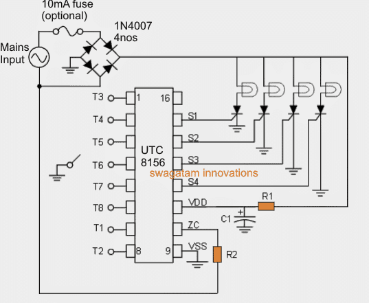
The following images show the basic functional and wiring details of the proposed 8 function Christmas light circuit.
Both the designs are basically the same, the first is based on the 18 pin IC, while the second one is configured using the 16 pin IC version.

How the IC Works
The pinouts of the IC on the left are designated with the "function" specs, which can be appropriately switched using a rotary selector switch whose pole can be seen connected with the ground or the negative line of the circuit for executing the selected function.
The circuit can be operated from any desired supply input source, as per individual preference, it can be operated from the mains 220V or from mains 110V input supply using the configuration depicted above, and also from any 5 to 24V AC/DC adapter unit.
The lamps must be rated as per the input supply used, meaning for 220V it should be 220V rated lamps, for 110V the lamps ought to be 110V rated, and for 24V it should be rated at 24V
For 220V and 110V operations the involved resistors and the capacitor might need to be changed appropriately as shown in the following table:

As per the specifications, the IC is able to operate even from supplies as low as 5V, which implies that the circuit can be possibly operated through a mobile charger.
About the SCRs
As can be seen in the diagram that the supply Vdd to the IC is substantially dropped through R1, which probably means that the current to the IC and for the SCRs could be very low, in the order of a few milliamps.
Therefore here the applicable SCRs could be the smaller ones which can work with 1 to 5mA gate current such as BT169, and hence the lamps would also need to be smaller in current, for example the 10 watt or smaller lamps.
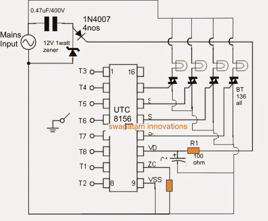
However, according to me the circuit can be appropriately modified for handling high watt mains bulbs simply by reducing R1 to 100 ohms and operating the circuit using a 5V cellphone charger and replacing the SCRs with C106 type of SCRs.
But with the above case the bulb top rail will need to be connected to one of the mains input for example the phase, and the negative common rail of the circuit will be required to be connected with the neutral line.
8 Functions Light effect
The IC is specified to generate the following 8 different light effect patterns as per the position of the rotary switch within the stipulated selection pinouts
1) The IC continuously scans and randomly generates the 8 functions in a row.
2) In this position the IC generates a wave like effect on the connected lamps.
3) In this mode the lights are illuminated in sequence one after the other and shutting off in the same order.
4) The fourth selection gives rise to a slow-glow kind of flashing visual over the connected lamps
5) Here the lights are switched off and ON with a chasing and simultaneously flashing style.
6) A quick switch ON of the lamps but a slow-fade effect can be witnessed in this position
7) The 7th preference produces a twinkling flashing effect on the lamps quite resembling the stars on the sky.
8) In the last mode the lamps actually do nothing but light up solid ON which also sometimes becomes useful for certain decorative applications.
For using the above Christmas tree light circuit with high watt AC lamps, the design could be modified in the following manner:
Courtesy: search.alkon.net/cgi-bin/pdf.pl?pdfname=utc/8156.pdf


Questions & Answers
Hi, I’ve already searched for the IC and I haven’t found it. But I’ll keep doing it. Bye
Thanks for your feedback, please do let us know if you are able to find it.
Hello, can the circuit be adapted for LEDs? And if so, how would it be done?
And in which store can I find the integrated circuit?
Hi, in the 8 Function Christmas Light Circuit, the bulbs can be replaced with LEDs after some modifications in the circuit.
You can Google the IC number and you may find some sources who are still selling this IC.
Namaskar Sir
Thanks for enhancement suggested.
It worked.
What will be the max current UM66 can tolerate if
1) we want to connect 3V adapter ?
2) 3.7V Li-Ion battery.
I will test neon at the earliest.
Thanks
Hi Sarang,
If you have a fixed 3v DC then current will not matter, you can use any current. it won’t harm the ic as long as the voltage is fixed at 3v. 3.7v li-ion battery will also be fine since um66 can handle upto 4.5v.
Namaskar Sir
Is it possible to build a circuit to FLICKER (Not flashing or not blinking) for 5mm LED and 5mm Neon bulb.
Thanks
Namaskar Sarang,
It may be possible…do you want both the LED and the neon together in one circuit?
Namaskar Sir
Thanks for your prompt guidance.
5mm LED flickering is successful with UM66T19LK.
It worked for only one LED at a time.
If we need to run 10 LEDs at a time , is it possible?
For Neon 5mm 3v um66 did not work.
Thanks.
That’s great Sarang, thanks for updating the results.
10 LEDs can be accommodated simply by amplifying the current using a 2N2222 transistor.
Connect the output of the UM66 with the base of the 2N2222 via a 1k resistor.
Connect the 2N2222 emitter with the ground line of the UM66 circuit.
Connect all the 10 LEDs between the positive supply and collector of the BC547.
That’s all.
Use 3V battery for powering the circuit.
Neon can be illuminated using a similar circuit as above by connecting a buzzer inductor between the positive and the collector of the transistor.
The neon lamp can be connected parallel to this inductor
Namaskar Sir
Thanks for reply.
Flickering led 5mm
and
Flickering Neon bulb both circuit separately..
Neon may be 1) 3v dc 5mm neon 2) 5mm ac neon
Thanks
Thank you Sarang,
Creating a flickering effect looks a little difficult, unless ICs are used.
The easiest way to achieve this is perhaps using an UM66 IC. Please try this. Take a UM66 IC, power it with a 3V DC, and connect an LED across its output and check the effect.
If it works, a neon circuit can be also configured using an inductor.
Namaskar
Great work.
Reg . 8 Function Christmas Light Circuit , Can you suggest a single chip(description) with push button circuit?Thanks
Hi, thanks, the circuit must be built
exactly as shown, it cannot be modified with a single push button.
Unless I am mistaken, an SCR can not be used with a DC supply as mentioned in the text, in the above example using a DC supply the SCR would latch on and never switch off. Other than that great job.
Yes that is correct, the SCRs must be replaced with transistors.
Good day my friend Swagatam!
I repeated your circuit with the IC4060. It works great.
Power supply I use – 12v and 3mm LEDs of various colors, installed 4nos in one row.
I used only 6 pins from the IC, because this design will decorate a mini Christmas tree only 8cm high.
Thank you for your hard work and the help you provide to budding electronics enthusiasts. Health to you and your family, good luck in the new year!
I hope that you will continue to delight us with simple but unusual schemes.
Respectfully,
Jorge
Thank you my friend Jorge,
I am g;ad you could make the project successfully.
Please keep up the good work.
All the best to you!
Cheers!
I accidentally bought a LED net that uses the ic4060 but runs off 220v mains. I don’t have time to be able to return them and get the version that runs off of 110v.so I was wondering if I can modify things to allow the system to work 110v?
I guess the circuit should work on both supplies 220V and 110V since an SMPS could be already installed inside…however without checking the internal details of the circuit it could be quite difficult to suggest about the modifications.
Excuse Swagatam, a clarification the capacitors C1-C2- 0,1 and 0,01microfarard are right?
Thank you
C1 is 0.01uF, and C2 is 0.1uF
Thank you, Swagatam for your very thorough and prompt reply.
Very professional, I have read some of your explanations on how the various projects work, I really like them they are clear and comprehensive, I think I will follow you pleasantly.
In fact, I’ll name you my favorite professor.
Another clarification if the LEDs connected in series to each pin were in parallel considering that each LED is 20mA what is the output of each pin in mA?
Plus if you can clear up a dilemma that has never happened to me
I have a polarization resistor on the base of transistor 2N4403 which is interrupted but I cannot obtain the value as it is composed with the following colors 1-Green band-2 Blue beams-3 GOLD band-4 GOLD band 5 Green band, since in all the handbooks of the colors of the resistors in the third band the color GOLD is not contemplated, in your opinion what value could it have?
Thanks again and good continuation of your work
Renzo Patrito
Thank you Renzo, I am glad to help!
The outputs from 4060 will produce less than 20 mA, so it can probably support only one string of series LEDs, adding parallel strings may not be possible directly with the pins.
It looks like the resistor value is 5.6 ohms, since the 3rd gold band signifies x0.1. So 5, 6, x0.1 gives 5.6 ohms
I hope this solves your problems.
Hi Swagatam, congratulations I found your Christmas light series circuit with the IC 4060 very interesting.
And just what is right for me.
I wonder with a 12 V power supply is it necessary to change the value of the resistors in series to each LED chain?
Does each series of LEDs have its own causal and non-sequential flashing?
Is it possible to mount 3.2v LEDs with others at 2.2v in each series of LEDs?
Also, if you mount 2 or 3 LEDs instead of 4, do you have to change the resistance value?
What voltage is there at the outputs of the 4060 and how many mA does it support?
If instead of using all 10 exits, 8 are used, can the other 2 be left free or should they be closed?
Hello Thank you very much for your interest in answering me.
Thank you Renzo, glad you found the circuit interesting!
With 12V supply you an change the resistor values to 56 ohms, since 330 ohms would make the light quite dim.
Each series of 4 leds will flash together, but each 4 led string at the different outputs of the IC will flash randomly depending on the flashing rate of the pinouts.
According to me you can use 3.2 V LEDs with 2.2V, but in that case you may have to increase the resistor value to 100 ohms
You can use 2 or 3 or even 1 LEd at each output, and that will require the resistors to be changed accordingly. Formula is R = Supply Voltage – total LED voltage / LED current
The voltage at the 4060 outputs are the same as the supply DC at its pin16.
You can use any number of outputs as you desire, it won’t affect the working of the IC.
I’m trying to get an Idea of how to make a 3-6v system of 5 randomized flashing White LEDs. I want them to be sporadic where more than 1 MAY be lit at a time, but no recognizable pattern exists. This would have to fit within an approximately 1″ x 2″ x 2″ space. What would be the simplest method for that?
You can build the 2nd design from this article
https://www.homemade-circuits.com/how-to-make-any-light-strobe-light/
It is a transistor astable. You will need 3 of these circuits, and put LEDs in series with R1 and R4 both. Then, you will get 6 LEDs that can be made to oscillate at different frequencies, as set by the respective C1, C2 values. This will simulate a random flashing effect across the LEDs
Thanks much. Do I need the BC 547’s or can I use some spare 3904 / 3906’s in their place?
Any general purpose NPN transistor will work. 2N3904 will also work
Hi Swagatam,
The above circuit shows 4 LEDs in series directly driven by the 4060 IC. Is this correct? Will the 4060 drive 4 LEDs in series without an external transistor? If they are Blue LEDs, what will be the current flowing through the 4060 with the 330R current limiting resistor (assuming a supply of 15V as your diagram shows)?I looked at an LED current limiting resistor calculator and it appears that the current of each LED would be 8ma. Will they be bright enough with only 8ma? I’m working on a project to flash 3 to four LEDs (depending on the color) in series from each output of the 4060 and I am using 12v supply. This circuit is very simple, but maybe I should consider transistors to get the power to drive the LEDs brightly. Your thoughts? Thanks!
Hi Norman, yes it will be bright enough for a 20 mA LED. Also, you can reduce the resistor values to 220 ohm to increase the brightness a little more.
If you want dazzling brightness then probably you may have to use an external transistor stage.
Can we increase the no.of led to 50 each
you will need transistor driver stages for that, on each channel.