In this post I have explained how to use resistors while designing an electronic circuits using LEDs, zener diodes, or transistors. This article can be very useful for the new hobbyists who normally get confused with the resistor values to be used for a specific component and for the desired application.
What is a Resistor
A resistor is a passive electronic component which might look quite unimpressive in a electronic circuit compared to the other active and advanced electronic components such as BJTs, mosfets, ICs, LEDs etc.
However contrary to this feeling resistors are one of the most important parts in any electronic circuit and imagining a PCB without resistors may look strange and impossible.
Resistors are basically used for controlling voltage and current in a circuit which becomes highly crucial for operating the various active, sophisticated components.
For example, a BJT such as a BC547 or similar may need a properly calculated resistor across its base/emitter in order to function optimally and safely.
If this is not followed, the transistor may simply blow off, and get damaged.
Similarly we have seen how resistors become so essential in circuits which involve ICs such as a 555 or a 741 etc.
In this article we'll learn how to calculate and use resistors in circuits while designing a particular configuration.
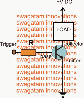
How to use Resistors for driving Transistors (BJTs).
A transistor requires a resistor across its base and emitter and this is the one of the most important relation between these two components.
A NPN transistor (BJT) needs a specified amount of current to flow from its base to its emitter rail or ground rail in order to actuate (pass) a heavier load current from its collector to its emitter.
A PNP transistor (BJT) needs a specified amount of current to flow from its emitter or positive rail to its base in order to actuate (pass) a heavier load current from its emitter to its collector.
In order to control the load current optimally, a BJT needs to have a properly calculated base resistor.
You may want to see an related example article for making a relay driver stage
The formula for calculating the base resistor of a BJT can be seen below:
R = (Us - 0.6).Hfe / Load Current,
Where R = base resistor of the transistor,
Us = Source or the trigger voltage to the base resistor,
Hfe = Forward current gain of the transistor.
The above formula will provide with the correct resistor value for operating a load through a BJT in a circuit.
Although the above formula may look crucial and imperative for designing a circuit using BJTs and resistors, the results actually need not be so much accurate.
For example suppose we want to drive a 12V relay using a BC547 transistor, if the relay's operating current is around 30mA, from the above formula, we may calculate the base resistor as:
R = (12 - 0.6). 200 / 0.040 = 57000 ohms that's equal to 57K
The above value could be assumed to be extremely optimal for the transistor such that the transistor will operate the relay with maximum efficiency and without dissipating or wasting excess current.
However practically you would find that in fact any value between 10K and 60k works well for the same implementation, the only marginal drawback being the transistor dissipation which may be slightly more, may be around 5 to 10mA, that's absolutely negligible and does not matter at all.
The above conversation indicates that although calculating the value of the transistor may be recommended but it's not entirely essential, as any reasonable value may do the job for you equally well.
But that said suppose in the above example if you chose the base resistor below 10K or above 60k, then certainly it would start causing some adverse effects to the results.
Below 10k the transistor would begin getting warmer and dissipating significantly..and above 60K you would find the relay stuttering and not triggering tightly.
Resistors for driving Mosfets
In the above example we noticed that a transistor crucially depends on a decently calculated resistor across its base for executing the load operation correctly.
This is because a transistor base is a current dependent device, where the base current is directly proportional to its collector load current.
If the load current is more, the base current will also need to be increased proportionately.
Contrary to this mosfets are entirely different customers. These are voltage dependent devices, meaning a mosfet gate does not depend on current rather on voltage for triggering a load across its drain and source.
As long as the voltage at its gate is over or around 9V, the mosfet will fire the load optimally regardless of its gate current which could be as low as 1mA.
Because of the above feature a mosfet gate resistor does not require any crucial calculations.
However the resistor at a mosfet gate must be as low as possible but much greater than a zero value, that is anywhere between 10 and 50 ohms.
Although the mosfet would still trigger correctly even if no resistor was introduced at its gate, a low value is strictly recommended for countering or restricting transients or spikes across the gate/source of the mosfet.
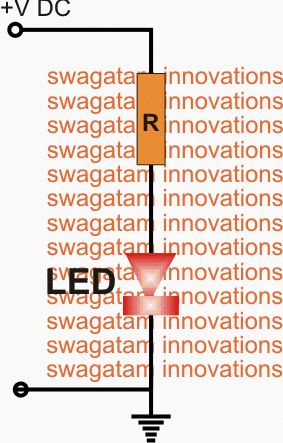
Using a resistor with a LED
Just like a BJT, using a resistor with an LED is essential and could be done using the following formula:
R = (Supply voltage - LED fwd voltage) / LED current
Again, the formula results are only for acquiring absolute optimal results from the LED brightness.
For example suppose we have a LED with specs of 3.3V and 20mA.
We want to illuminate this LED from a 12V supply.
Using the formula tells us that:
R = 12 - 3.3 / 0.02 = 435 ohms
That implies that a 435 ohm resistor would be required for obtaining the most efficient results from the LED.
However practically you would find that any value between 330 ohm and 1K would render satisfactory results from the LED, so its just about little experience and some practical knowledge and you could easily get across these hurdles even without any calculations.
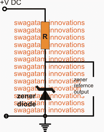
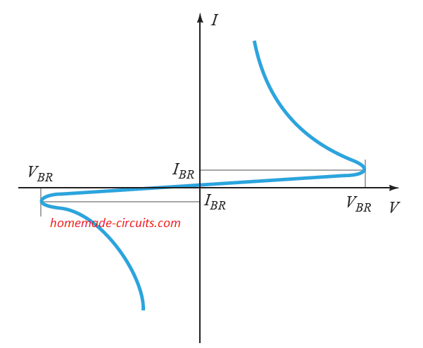
Using resistors with zener diodes
Many a times we find it essential to include a zener diode stage in an electronic circuit, for example in opamp circuits where an opamp is used like a comparator and we intend to employ a zener diode for fixing a reference voltage across one of the inputs of the opamp.
One may wonder how a zener resistor can be calculated??
It's not difficult at all, and is just identical to what we did for the LED in the previous discussion.
That is simply use the following formula:
R = (Supply voltage - Zener voltage) / load current
No need to mention that the rules and parameters are identical as implemented for the LED above, no critical issues will be encountered if the selected zener resistor is slightly less or significantly above the calculated value.
How to use Resistors in Opamps
Generally all ICs are designed with high input impedance specs and low output impedance specs.
Meaning, the inputs are well protected from inside and are not current dependent for the operational parameters, but contrary to this the outputs of most IC will be vulnerable to current and short circuits.
Therefore calculating resistors for the input of an IC may not be critical at all, but while configuring the output with a load, a resistor may become crucial and may need to be calculated as explained in our above conversations.
Using resistors as current sensors
In the above examples, especially for the LeDs and the BJTs we saw how resistors could be configured as current limiters. Now I have explained how a resistor may be utilized as a current sensors:
You can also learn the same in this example article which explains how to build current sensing modules
As per Ohms law when current through a resistor is passed, a proportionate amount of potential difference develops across this resistor which can be calculated using the following Ohms law formula:
V = RxI, where V is the voltage developed across the resistor, R is the resistor in Ohms and I is the current passing through the resistor in Amps.
Let's say for example, a 1 amp current is passed through a 2 ohm resistor, solving this in the above formula gives:
V = 2x1 = 2 V,
If the current is reduced to 0.5 amps, then
V = 2x0.5 = 1 V
The above expressions show how the potential difference across the resistor varies linearly and proportionately in response to the flowing current through it.
This property of a resistor is effectively implemented in all current measuring or current protection related circuits.
You may see the following examples for studying the above feature of resistors, all these designs have utilized a calculated resistor for sensing the desired current levels for the particular applications..
Universal High Watt LED Current Limiter Circuit - Constant ...
Cheap Current Controlled 12 Volt Battery Charger Circuit ...
LM317 as a Variable Voltage Regulator and Variable ...
Laser Diode Driver Circuit - Current Controlled | Homemade ...
Make a Hundred Watt LED Floodlight Constant Current ...
Using resistors as Potential Divider
So far we saw how resistors can be applied in circuits for limiting current, now let us investigate how resistors can be wired for getting any desired voltage level inside a circuit.
Many circuits require precise voltage levels at specific points which become crucial references for the circuit for executing the intended functions.
For such applications calculated resistors are used in series for determining the precise voltage levels also called potential differences as per the circuit's requirement. The desired voltage references are achieved at the junction of the two selected resistors (see figure above).
The resistors which are used for determining specific voltage levels are called potential divider networks.
The formula for finding the resistors and the voltage references can be witnessed below, although it may be also simply achieved using a preset or a pot and by measuring its center lead voltage using a DMM.
Vout = V1.Z2/(Z1 + Z2)
Have further questions? Please jot in your thoughts through your comments.

Questions & Answers
Hello sir please which resistor value can I use to step down 220v to 210v and how can I calculate it
Adeyemi, please see the formula, you can easily solve it for getting the required results.
I believe there is an error in the use of Ohms law where you wrote (twice) V = I/R instead of V = IR
—
Let's say for example, a 1 amp current is passed through a 2 ohm resistor, solving this in the above formula gives:
V = 2/1 = 2 V,
If the current is reduced to 0.5 amps, then
V = 2/0.5 = 1 V
—
thank you for pointing it out…will correct it soon.
Sir,
i would like to design a digital attendance register for my department using fingerprint as a module.
i would like to design a different things among my coursemates.
please assist me with the working circuit for this project.
Best Regards
Kevin,
please specify your requirement in detail, I'll try to help and also provide the datasheet link of the fingerprint module
How can I calculate the resistor value for the scr gate. When using on AC load
….sorry R = V/I
same as DC…using Ohms law R = I/V
I = minimum gate triggering current spec (from datasheet)
V = gate supply voltage
Nice thank you
Sir if I connect the dc load between ground and cathode and connect Positive to the anode, is it okay? As I have seen other circuits with this configuration.
In your circuits with scr you have connected the dc load between Positive and anode and cathode to the ground
is there any difference
Mujahid, the gate signal needs to find a clean (direct) path to ground that's why load is not recommended at the cathode of an SCR…
In case of an scr, which direction the current will flow, from cathode to anode Or anode to cathode?
from cathode to anode…
THANK YOU
Sir which direction will the current flow "From positive to negative Or from Negative to Positive if a load is connected to a battery(dc power supply)
we imagine it to be from positive to negative for convenience, but the actual "electron" flow is from negative to positive.
Actually sir my question is about the NPN Transistor BC547. An npn transistor is used to control the negative to the load but here you have used an npn transistor to control the Positive voltage to trigger the scr. Can we use an npn transistor to control positive voltage? This is my question. I don.t know about it
what you are referring to is a common emitter configuration, which is the most common one, but the SCR circuit is rigged with a common collector configuration, so that's the only difference.
It's all about tracking the voltage from the collector to the emitter path, and taking the output from wherever it appears suitable for a particular application.
Sir whatever I know about a transistor is that its emitter is connected to the supply line and collector is connected to the load and base is connected to the triggering voltage in series with a resistor. Now come to the configuration around a transistor used in your Rain Alarm circuit with an SCR. I don.t know about this configuration. Kindly explain
It's configured as an emitter follower or a common collector…….
Mujahid, as long as there's no base voltage (no rain), the emitter is also rendered at 0V, which keeps the SCR switched OFF….but as as soon as water is detected at the transistor base, it's potential rises, and the emitter also turns positive, triggering the SCR and the alarm:
https://www.homemade-circuits.com/2012/03/how-to-make-simple-scr-application.html
Then I could not understand the configuration around your designed CODE LOCK CIRCUIT WITH SCR. Kindly explain. THANK YOU.
It is not configured with a 100% efficiency, may be with only 50% efficiency…but it appears to be enough for the relays to trigger and therefore it's serving the purpose…and it's the only way the design could be implemented with minimum complexity…..
In few of your circuits like Rain alarm and burglar alarm using scr. You have controlled the negative to the load by using SCR connecting cathode to the negative and anode to the load.I would like to know whether I can control Positive to the load by connecting anode to positive and cathode to the load?
load is always recommended to be in between anode and positive..otherwise the SCR will not operate efficiently.
Sir kindly let me know which pulse is required to trigger an scr at its gate Positive or Negative?
it's always positive….
How to determine the resistor value for scr gate
by using Ohms law, the triggering current (I) can be identified from the datasheet of the scr
Maybe I control it by push button or by configuration around ic 4017 and transistors step by step
you can do it by associating each 4017 output with presets, all the slider arms will connect with the TIP 122 via diodes….other two terminals can go to the 4017 pinouts and ground.
I made one of your voltage regulator circuit with tip122. It.s working nice. The resistance to the base is increased or decreased manually which regulates the voltage accordingly but if I increase or decrease this resistance via transistors step by step.is it all possible? If yes then how would be the configuration?
you want to control with a push button?
I want to make a battery level indicator circuit with ic lm324. Is it possible to use a single zener resistor network as a fixed reference for all stages
a single zener can be used as the reference….but fixed resistor for all the opamps will not be possible…
Sir in one of your Low Battery Indication circuit with ic 741 it.s all working well but when I replaced the led with a piezo buzzer there was no audible response. What may be a possible cause?
where did you connect the piezo buzzer?
Ic like 4017 which gives sequential output, if I have to drive a relay through pin 3,4 and 7, should these pins have their own resistor or a single resistor is enough for transistor base
if you are using separate relay driver stages on each pin then separate resistors would be required….
To control heavy AC load generally mechanical relay or mostly contactor are used why not solid state relays?
Are they not durable or unable to control heavy AC load.
solid state relays can be extremely costly…and require an electronic circuit for the operations, in contrast the contactor is much cheaper and works without the need of an electronic trigger
What is the maximum output (amp) of a transformerless supply?
If i use a zener diode for the required voltage should I use a resistor in series with zener
you can find the required info here:
https://www.homemade-circuits.com/2011/12/how-to-calculate-and-deduce-current-and.html
resistor in series is not required
A battery is described 7ah, 40ah 150ah what this" amp hour "really means
ideally a 7AH battery is supposed to last for 1 hour when discharged at 7 amp rate
Sir if I connect one amp dc load to a 7Ah battery then how long the one amp load will run? I mean to know time.
It will depend on the battery condition, in ideal conditions the backup could be up to 5 to 6 hours
I want to ask a question not related to the above post. I want to run 500watt load by an inverter. I want to know the capacity of a 12v battery that could run the 500watt load for an hour. any formula?
if you divide 500 by 12V, it comes to approx 42 amps…so the minimum battery capacity should be 42 AH, but this will allow the inverter to run only for approx 1/2 an hour…so for getting some reasonable back up time the optimal batt AH must be around 150AH
Thank you.