In this post I have explained a typical grow light circuit application for plants in order to stimulate photosynthesis effect in an artificially lit environment using multicolored LEDs. The idea was suggested by Mr. Jack.
The Circuit Objective
I would like to donate to your site and pay you also for work you do on projects here. But first, to receive money from individuals on the web you will have to get a Pay Pal account.
Once this is established, you will have to decide how you would like to operate it. You provide thousands of people from all over the world with technical information to make there life better, there is no reason not to have a "donate page" to make your life better also.
That is unless you are independently wealthy. You have web site costs, food, living expenses, travel, etc.
I will gladly share my projects with you. You can post them on your site. Here in the USA, residential LED lightings has not caught on yet and there are many reason for this.
Commercial lighting is even worse. Electricity is really a big mystery to most of the average working class people and they feel it is best to avoid it if possible.
I have several friends who are very successful, and do no know what a "watt" is. That is OK. But not being aware slows down our evolutionary process. The very poor people are the last to enjoy the benefits. The very big corporation have enslaved us all. This will change soon.
I have a "grow light" project I'm just finishing up and can send you the details and pics if you'd like. My grow light is a 28 led mix (red, blue, white) that will cost me about $30 and the same light runs $300 -$500 in some on the large lighting companies.
The big problem with "grow lights" and I'm sure your aware of this, is the different forward voltages of the different colors, i. e., red (1.63v-2.03v) and blue (2.48v-3.7v).
Having red and blue in the same circuit, there can be 1v to 1.5v difference in forward voltages. In the circuit I just built, I have the red lights operating at 1.7v and the blue operating at 3.5v, this difference causes much heat.
I can solve the problem by putting each on there own circuit but I don't wish to do that yet. I'm using 16 ohm, 10w power resistors (7 leds in series per row, and 4 rows) at the start on each row.
Even they get hot. Need to balance this circuit. I'm using a DC power supply 24v and 4amps to power the circuit.
The next project will be several large lights for my shop,.........50 - 60 led fixtures. After that will be to put in advanced LED lighting in a warehouse - office complex these will be 50 - 200 led lighting fixtures. I'm looking to use 120vac - 220vac to supply the power.
Is it possible to design a led driver circuit (LDC) on a single IC chip??? I know it can be done. How about making an LCD eprom??
Let me know if you'd like to post the grow light experiment.
Best regard,
Jack
.....I just discovered why my grow light circuit is producing so much heat. It is caused not only by the forward voltage difference between red and blue lights but by the imbalance of my series strings.
In other words, if I have a different number of blue light in each string, than I will get heat build up. If I make the number of blue light the same in each string than it should work. You probably know this already.
Analyzing the Circuit Request
Thank you Jack, I'll provide you with the formula for calculating the series LED resistances so that you can balance the LEDs correctly and obtain optimal performance from them
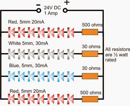
R = (U - Tot.LEDfwdV) / LED current.
In the above formula U is the supply voltage, Tot.LEDfwdV is the combined or the total forward voltage value of the particular LED series, and LED current is the LED amp rating.
In your case for the red LED the formula could be solved in the following way:
Let's assume U = 24V, Fwd voltage = 2V, total number in the series = 7, and LED current = 20mA or 0.02amps
R = {24 - (2x7)}/0.2
= (24 -14)/0.02
= 10/0.02
= 500 ohms
wattage may be calculated using the formula
W = Tot.LEDfwdV x LED current
= 14 x 0.02 = 0.28 watts
You just have to follow the above calculation procedures for each of your LED series and position the calculated resistors in series with the particular color strings.
I hope it won't be too difficult for you to do this. If you have problems please do let me know.
The circuit diagram for the proposed grow light may be witnessed in the following diagram.
Basic Circuit Diagram
In the above sections I have explained how to wire a low power grow light circuit using 5mm LeDs, here we see how the same may be done using 4 watt power LEDs. The idea was suggested by Mr. Jack.
Technical Specifications
Hello Swag,
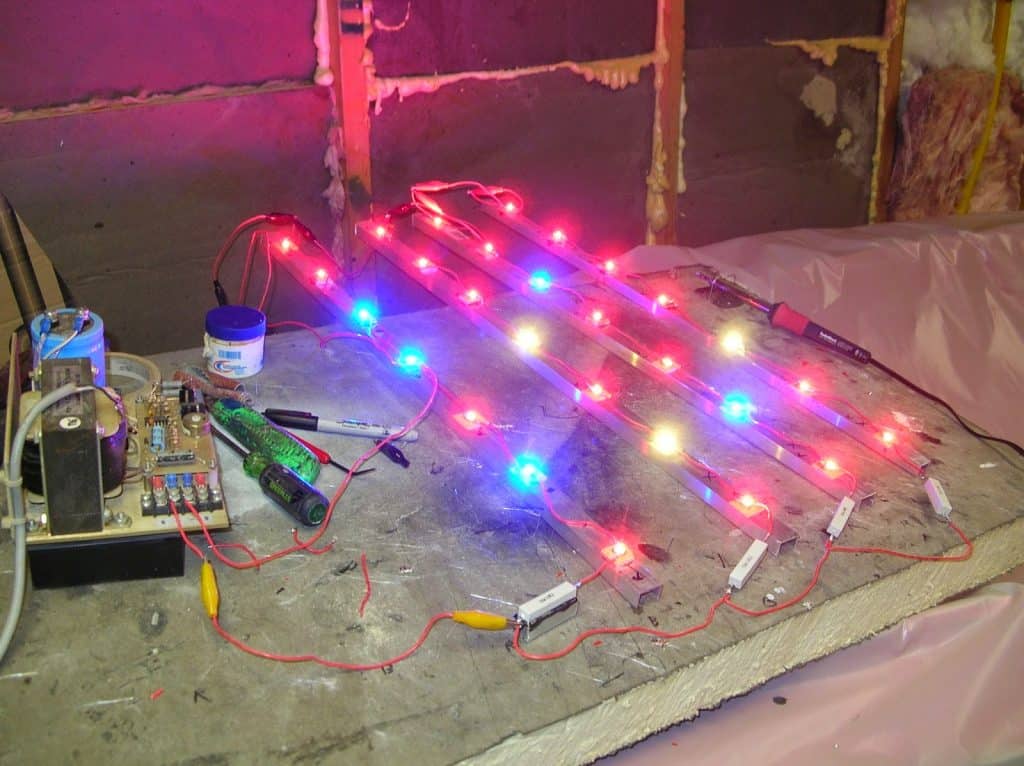
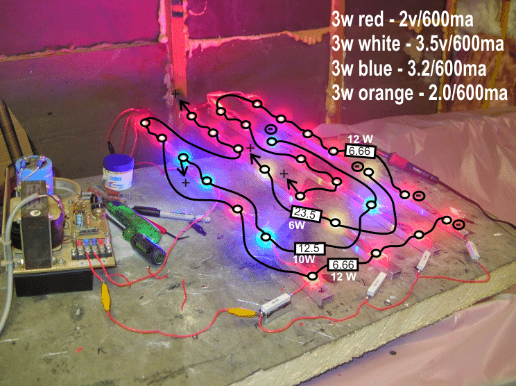
During my exploration of LED lighting and the various circuits employed I would like to post some of my recent finding. Acknowledgements to LED Magazine and Steve Roberts. I've attached several pictures of my recent build,.....28 - 3watt leds, 7 leds, in series per row and 4 row in parallel. I'm using a 24v-32v, 4amp power supply.
These lights were purchased as emitters and the bases had to made and heat sinks applied to each emitter. The leds were mounted to aluminum channel.
Since the completion of the circuit, I've experienced various heating problems and it was continuing to be difficult to balance the circuit, to run cool, stable, and steady electronic output. I decided to look deeper into this and leds in general and here is what I've found.
Even if the LEDs are all from the same production batch and sequentially manufactured, the foward voltage (Vf) of individual LEDs still has a ± 20% tolerance.
The tolerances this high means that the total forward voltage for each led in a string can be very different and therefore the current mismatch can be very significant.
Consider, if we have 5 leds in series with a forward voltage of 4v, that is (4v)(5) = 20v. WRONG!!!
Given the tolerance above, the forward voltage is really, 16v to 24v, that an 8v spread. How are you going to design a circuit that requires you to place things in BALANCE if the tolerances are that hight? This is one of the reasons that things go array. There are many others!!!
Jack Sturgeon
For a newcomer or a new hobbyist wiring LED lights could look complex with many hidden intricacies, actually it's not.
Wiring the LEDs
It just needs to be done as per the rules, for getting the correct results.
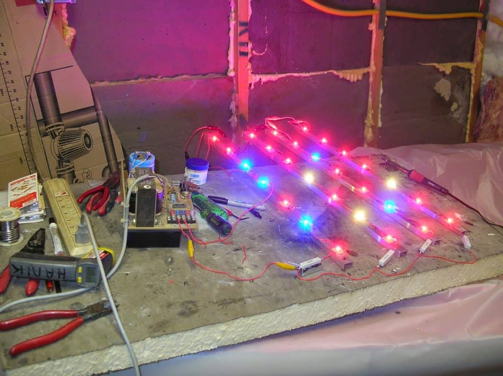
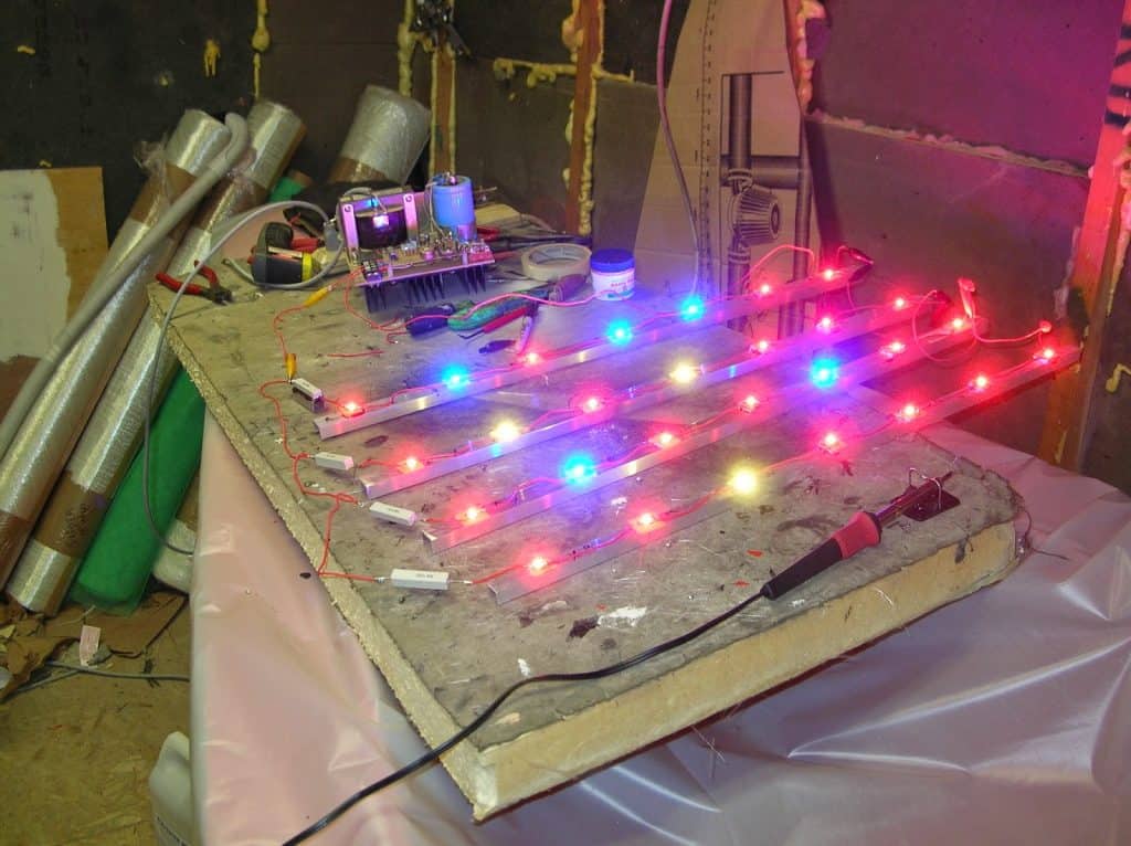
Referring to the above images sent by Mr.Jack, we can see that the LED strings are not correctly wired and that's exactly why the design is giving erroneous and erratic response.
You should never wire LEDs having different V/I specs in series.
You should always group up the LEDs with identical specs together when a series connection is needed to be implemented.
However if the requirement is in a mix and match manner as in the above images, yet still the same color LEDs must be connected in series and if necessary in parallel with their individual series resistors.
High watt LEDs will emit heat, therefore assembling these devices over a heatsink is imperative and to avoid a thermal runaway we can incorporate a current regulator, that's all right, no issues with these parameters.
But said that the LEDs must be wired up as instructed in the above paragraphs, only then you would be able to acquire an efficient response from the system.
And suppose you have a power supply which is rated to supply a lower voltage but higher current in that case you could simply hook up all the LEDs singly in parallel with each LED equipped with its own limiting resistor, a well calculated one.
Calculating the LEDs for the grow light circuit using power LEDs
I have already discussed this in one of my previous posts, you may read it here
Therefore the correct way of wiring the LEDs for the above example high power grow light assembly should be as expressed in the following diagram.
All the positive and negative ends of the respective strings now simply needs to be integrated with the power supplies (+)/(-) terminals
If you have any questions or doubts feel free to post them in the comment box below.
I think I completely missed something in the above design.
Since the current specs of all the LEDs are same, voltage specs can be ignored, and different color LEDs may be connected within the same strings.
So let's analyze the design correctly yet again.
The first string from left has 4 red LEDs and 3 blue LEDs, supply is 24V, therefore the current limiting resistor for this string could be calculated as follows:
R = supply minus total LED fwd. voltage divided by LED current
= 24 - (4x2)+(3x3.2) divided by 0.6 (600mA)
= 10.66 ohms
wattage =(4x2) + (3x3.2) x 0.6 = 10,56 watts
you can calculate resistors for the other strings too, in the above manner.
The current control for the above set up can be constructed as explained in the following artices:
https://www.homemade-circuits.com/2013/06/universal-high-watt-led-current-limiter.html
https://www.homemade-circuits.com/2011/12/make-hundred-watt-led-floodlight.html


Questions & Answers
HI Swagatam!
Tremendously proud of what you have achieved here!
I’m not from an electronics background, and am trying to best to figure out how LED boards are wired, and how to match drivers to them. Plus the advantages and disadvantages of the various options.
My interest lies in grow lights, specifically using thee newer midpower LED, such as the samsung LM561c.
Thank you once again!
Any guidane towards the samwould be much appreciated.!
Thank you Sidhu, appreciate your feedback.
For any power LED there are 3 basic things that must be included to enable safe operation of the device.
1) The input supply must be rated with a controlled constant voltage which must be precisely equal to the optimal voltage rating of the LED.
2) The input supply must be also rated with a controlled constant current which must rated precisely or lower than optimal range of the LED.
3) The LED must be mounted on a heatsink if it shows a heating up tendency within few seconds. If not then heatsink can be ignored.
You can use a standard LM338 or LM317 IC circuit for implementing as detailed in the following article:
https://www.homemade-circuits.com/3-watt-5-watt-led-dc-to-dc-constant/
Thanks super Swagatam! Ill be around!
You are welcome Sidhu!
At first thanks a lot to Swagatam for sharing such a useful and I have pleased to get this blog page. I have read your informative and valuable page and gotten much information. But I have two questions that how many LED grow lights are appropriate per square foot for indoor plants? And what watts need for indoor tomato plants? Could you please suggest me? Then I will be benefited by your valuable suggestion.
Anyway, I will save your site and I will share it with my friends. I hope they will be benefited by this article.
Thank you so much Jessica, I am glad you liked my site. However I am not sure about the grow light specifications for the various plants, because my expertise is restricted to designing circuits only.
Welcome and Thanks again for your valuable opinion.