The article details a circuit design for controlling a washing machine motor agitator through a preset time sequence which also includes an alternate reversing of the motor rotation. The circuit was requested by Mr. E.Rama Murthy.
Technical Specifications
I am having old washing machine which is good working till now. Of late, its PCB has gone and I am not able to get it locally.
The mechanical/electrical working is good. The timer is electrical-mechanical and is working okay. What I need is a circuit or your made-item with the specifications as below.
It could work on 220 volt ac or I can provide 5Volt dc supply thru local power adaptor. The unit should have for operating of motor, 2 nos separate relays for running the motor forward and reverse.
The timing for the operations of relays is 2 secs stop and 5 secs forward and 2secs stop and 3 secs reverse. This is for working of clothes agitation process.
The motor is 0.5 hp. I should be able to enclose it in a box which is water-proof. Kindly let me know how much I should send you by way of bank transfer, which should include your packing and forwarding charges.
Thanking you in advance.
E.Rama Murthy., Visakhapatnam., A.P.
Understanding Washing Machine Motor Wiring
Before I have explained how to make a customized timer controlled washing machine unit, it would be important to learn the basic diagram of a 3 wire washing machine motor.
As shown in the below diagram, a washing machine motor typically has a couple of identical sets of winding. Unlike fan motor, the two winding are identical in terms of wire thickness and number of turns.
This is because a washing machine motor has to rotate in both ways. Meaning, it has to move anti-clockwise and clockwise alternately.
Therefore, the wiring is implemented in such a way that the each winding works like a main winding as well as capacitor start winding alternately, depending on which winding is selected by the timer relay.
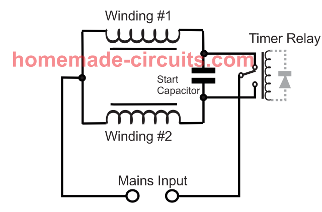
How Reverse Forward Rotation is Implemented
In the image above, assuming the winding #1 is selected by the timer relay, causes the winding #1 to act like the main motor winding, while winding #2 works like a supporting capacitor start winding, for initiating the motor rotation in a specified direction.
Next, when the timer relay connects with the winding #2, this winding now becomes the main winding and winding #1 is used like a capacitor start winding for turning the motor in the opposite direction. In this way a washing machine motor is able to rotate in a reverse/forward direction despite of being an AC motor.
Designing the Circuit
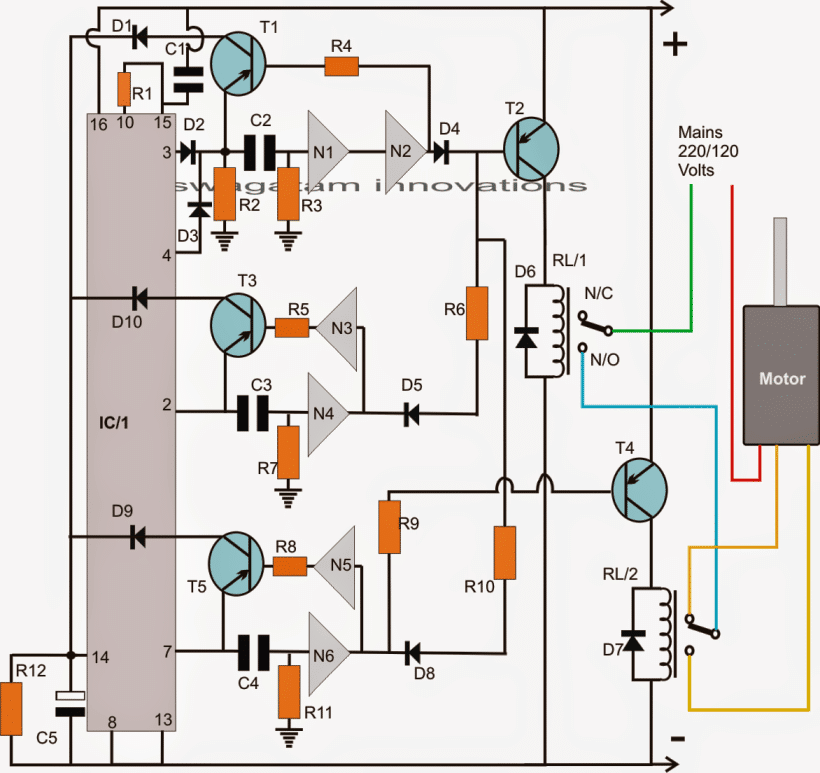
The proposed washing machine motor agitator controller circuit functioning may be understood as I have explained below:
When power is switched ON to the circuit, pin15 of IC gets reset by C1, rendering a high at its first pin#3 which is the first pinout in the order of sequence for the IC 4017.
The above high logic at pin#3 instantly passes through C2 causing a logic high at the input of N1 which in turn causes a logic high at the output of N2.
The above situation keeps T2 and RL/1 switched OFF.
Now after a predetermined time of 2 seconds which can set by appropriately selecting the values of C2/R2/R3, C2 becomes fully charged rendering a logic zero at the input of N1 which instantly changes the states at the outputs of N1/N2 causing a logic zero at the output of N2 which in turn switches ON T1.
T1 passes a short positive pulse via pin#3 high across its emitter/collector to pin#14 of IC1.
The above pulse clocks IC1 so that the logic high pin#3 now shifts to the next pinout in the order, pin#2.
The above high at pin#2 identically passes on at the input of N3 rendering an instant low at its output. This low triggers T2 and RL/1 activating the motor in a particular direction depending on the wiring of RL/2 contacts.
N4 holds the above logic state until 3 seconds is lapsed which is determined by the values of C3/R7, after which N4 reverts its state switching ON T3, which causes a short pulse to pin#14 of IC1.
The above pulse once again clocks IC1 so that the logic now shifts from pin#2 to pin#4 in the order of the sequence.
Pin#4 high yet again repeats the first sequence which was implemented when the logic was at pin#3.
The above conditions deactivates RL/1 and the motor for another 2 seconds.
After the above 2 seconds has elapsed, T1 switches ON providing a pulse to pin#14 which results in the shifting of the sequence to pin#7.
The high at pin#7 yet again switches ON T2/RL1 and also RL/2. However this time the motor changes its rotational direction due to the activation of RL/2.
C4/R11 values make sure that the above condition stays ON for about 5 seconds. After 5 seconds T5 performs the clocking of pin#14 which shifts the sequence to the next pinout order that is at pin#10. Since pin#10 is connected to pin#15, the situation instantly bounces of and resets back to pin#3....and the cycle repeats.
Circuit Diagram
Parts List for the above washing machine controller timer circuit
- R1, R4, R5, R6, R8, R9, R10 = 10K
- R2, R3, R7, R11, C2, C3, C4 = TO BE DETERMINED BY TRIAL AND ERROR
- R12 = 100K
- C5 = 33uF/25V
- T1, T3, T5 = BC557
- T2, T4 = 2N2907
- D1----D10 = 1N4007
- N1----N6 = IC 4049
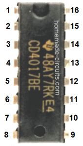
- IC1 = 4017
- RL/1, RL/2 = 6V/100mA RELAYS SPDT
How to Wire the washing machine motor connections.
As shown in the above diagram, the motor would have three wires, one of them would be the mains input while the other two for the flipping action or for reversing the motor directions.
You would want to take the help consult a qualified washing machine repair technician for confirming the exact wire inputs before connecting them with the circuit.


Comments
sir I need fully automatic top loading washing machine wiring connection and PCB design easier to learn. I m mechanical engineer
Hi Jyoti, sorry, I do not have this circuit with me at the moment…
Hello, I have a universal washing machine motor (230VAC) with a tacho gen on the back side of it, I would like to use it but was told that it must be operated with a control circuit that is governed by the tacho gen. do you know where I can find a circuit diagram of such a control circuit? Thanx.
Hi, sorry I have no idea about the circuit diagram that you have mentioned!
appricate Sir
Have made this but relay burns out in 15 /20 days.
It’s because you might have used an underrated relay….try a 30 amp relay
okay will try now it is 8 amp relays for 500 watts motor.
use 30 amp relay contact for guaranteed safety
Thanks.
I am regularly using your circuits its quiet useful.
Thank you, glad you found the circuits useful.
SIR/I AM R.KRISHNAMOORTHY A RETIRED ENGINEER/PROFESSOR IN ELECTRONICS.I AM ALSO KNOWLEDGABLE IN HARDWARE/SOFTWARE.NOW I REQUIRE AN EMBEDED SOFTWARE PROGRAM EITHER FOR A 8051 OR PIC16F887 FOR MY WASHING MACHINE.THE PARAMETERS
MAY BE NORMAL FOR WASH/DRY CYCLES.THE PROGRAM MAY BE IN ASM OR C.WILL YOU BE ABLE TO HELP ME OUT.I EXPECT YOUR REPLY SOON.WITH REGARDS R.KRISHNAMOORTHY.
Sorry Krishnamurthy, I do not have any microcontroller based washing machine motor controller circuit at this moment.
Same like Manish Gupta’s requirement
Hi , why do we need to control the motor for washing machine. I mean why is it necessary to develop motor controller circuit for washing machine.
Hi. I am K.R.Vasudevan. The purpose of washing machine timer circuit is to convert the front load washing machine to semi automatic. I don’t know why the machines PCB created problems. Every times the service personnel are charging heavy amount. So I planned conversion.As I am an Electrician and have some knowledge of electronic, I planned this decision. I am a senior citizen 68 year old, consider this not only as a time pass but also as a hobby. Please help me for the conversion. Thanks
Hi KR, please tell the sequence of the motor that you want to implement, and which section should be automatic and which section manual, I’ll try to figure it out!
Thank you for your kindness. The capacity of the universal motor is 500 watt.(230v,3 wire, one common and forward/reverse ) Water fill and drainage will do manually.washing and spinning if automatic can arrange, its fine. Otherwise washing must in automatic with forward/reverse rotation within 15 to 20 seconds and 5 second intervals. Maximum washing time not more than 20 minitus or around.If spinning can arrange, time may set around 10 to 15 minutes including drying.I think that a variable speed control unit is must for washing and spinning/drying.This can operate by manually with the help of two way switch. You can change anything as per your choices.
OK I’ll try to solve through a simple circuit, but it will be automatic only for the reverse forward washing section, the other sections will be manual to keep things uncomplicated.
I am waiting for circuit.
I am providing the diagram for all, below:
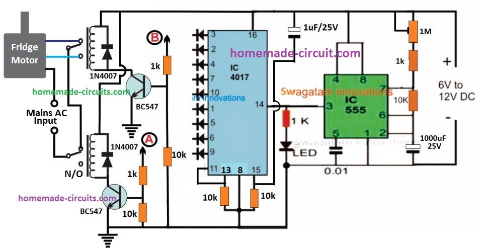
Join all the cathodes of diodes at pin3,7,5 and connect the common end with poin (B)
Join all the cathodes of diodes at pin4,1,9 and connect the common end with poin (A)
Thank you sir.
It’s probably to enhance the washing procedure, and clean the clothes more effectively within shorter duration of time.
To use polarised capacitor for c2 and others where will the + and – leg be
Can I use 0.22uf/250v for c1
0.22uF will work, but for assured resetting I would recommend a little higher value, may be a 0.47Uf or 1uF, ….voltage rating can be anything above 25V…
The positive leg will be towards the IC pins.
Thank you Swag, I have built this circuit but it is not working, it is complex to troubleshoot, please which points can I test to solve it.
Glory, the circuit can be complex for a newcomer. You will have to proceed stage wise.
The gate circuit connected with the IC 4017 are basically delay timers, and their working must be confirmed first.
So you can begin by concentrating on the T1, N1, N2 stage only, ignore all the stages built around T2, T3, T4, T5.
Connect an LED across collector of T1 and ground via a 10K resistor. Use relatively bigger values for R2/R3/C2 so that the delay is longer is distinguishable.
Use 1M for R2/R3, 10uF for C2.
Also connect LEDs with 10K resistor across pin#3 and ground, pin#2 and ground of IC 4017
Now switch ON power.
You will find pin#3 LED lighting up first and after sometime the collector LED will light up and then quickly shut off itself and the LED at pin#3, but this will immediately switch ON the LED at pin#2. And the system will end there.
First confirm this stage then we can proceed ahead.
Is it towards ic4049 or ic4017.
towards IC 4017
Dear Swagatam,
The circuit given is fantastic. It would be really a replacement for the washing machine mechanical timers. What I would request is the timer circuit which can be used for any application. The following is what I need. If you could provide it would be great.
1. After switching on the timer should be set for 15 mins. (the motor should be on for 15 mins)
2. After this first 15 mins are over (motor should stop for say 5 mins.
3. After this 5 mins of motor stoppage , it should run for another 8 mins.
4. after this 8 mins the system should stop by giving a buzzer sound.
If a counter for no. of cycle to be counted is possible it would be great but not compulsory.
the timings i.e 15 mins, 5 mins and 8 mins should be able to set by presets…..
Thank you dear Milind, I am glad you liked the circuit.
The requirement which you have mentioned can be very easily implemented by using 3 IC 4060 timer circuits in series.
A two way system is shown below, this can be upgraded to a 3 sequence by adding one more stage… if possible I’ll update it here for you.
https://www.homemade-circuits.com/how-to-make-simple-programmable-timer/
Is your prototype works well?
HELLO Hope you will be fine.
sir i have final year project in this semester that is fully automatic washing machine.we buy a old body of that machine and remove controller of that machine. because we are going to programing on repberi pi. to control that machine. sir we have issue regarding controller circuit i mean how we can make that and also issue in universal ac motor controllering. if you can regarding this point so we will very thank full to you
Hello,
please provide all the details regarding how the motor is supposed to move…and I think a DC motor will be more easy to operate and control than an AC motor.
DC motors are easier to control either ways (reverse and forward) compared to an AC motor
site check
I want to build a circuit for turning eggs in an incubator. It turns every three to 4 hours .i.e. The interval between turning is 3 to 4 hours can u please help me with a circuit diagram?
please use the search box for finding it…it's already posted in this blog
Dear Swagatam,
Value of C1 is not clear please tell me value of Capacitor C1
you can use 0.22uF there…..
Sir, I wants to ask resistors value in Ohm
take R2, R3, R7, R11, = 22k ohms
and C2, C3, C4 = 10uF/25V
but I don't know what time sequence this will generate…
Dear Swagatam
will you tell me approx what capacity of R2, R3, R7, R11, C2, C3, C4 should i use for my purpose as given above
can i use variable resistors instate of R2, R3, R7, R11 if yes then what capacity of variable resistor should i have use.
….C5 is an electrolytic capacitor
Dear Manish, all the resistors are 1/4 w rated…all the capacitors are "disc ceramic" types.
first check the circuit response using fixed resistors, if everything work fine then you can try replacing those with variable resistors.
you mean i have to connect the ic pins in this sequence:
N1—3,2
N2—5,4
N3—7,6
N4—9,10
N5—11,12
N6—14,15
but what to do with remaining pins 1,8,13,16
yes yuo can do it in that way…….other than the gates look for the supply +/- pins of the IC and connect them accordingly…. ignore the rest of the pins.
one could use a PIC and some coding..???
you can check the datasheet of the IC, you will find 6 triangle shaped gates in it having single inputs and outputs….use these gates as shown in the above diagram
all the gates are identical so these can be configured as one may choose…just make sure the input and the output pins are correctly positioned….also identify the (+) (-) of the iC and connect those with the supply rails…