• Skip to main content
  • Skip to primary sidebar

Homemade Circuit Projects

Need circuit help? Post them in the comments! I've answered over 50,000!

Blog | Categories | About | Contact | Calculators-online
You are here: Home / Datasheets and Components / Vibration Sensor 801S Datasheet Explained

Vibration Sensor 801S Datasheet Explained

Last Updated on July 17, 2023 by Swagatam Leave a Comment

The 801S vibration sensor is a typical vibration detection and measurement module. The following are some of its main technical features, datasheet and characteristics:

Table of Contents
  • Datasheet in Details
  • Conclusion

  • Sensor Type: Vibration sensor
  • Operating Voltage: 3.3V - 5V
  • Output Signal: Digital output (high or low)
  • Sensitivity Adjustment: Potentiometer for sensitivity adjustment
  • Detection Range: Adjustable, typically up to a few meters
  • Frequency Response Range: 0.5 Hz - 10 kHz
  • Operating Temperature Range: -10°C to +70°C
  • Dimensions: Typically a small module with compact dimensions
  • Connector Type: Typically a 3-pin interface (VCC, GND, and Signal)
  • Supply Current: Typically less than 2 mA
  • Noise Level: Low noise output for accurate vibration detection
  • Response Time: Fast response time for detecting vibrations
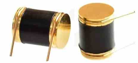
image of 801S shock sensor

Datasheet in Details

The 801S vibration sensor is very sensitive and can pick up even the smallest vibrations in its surroundings.

Frequency Range: The module is made to detect vibrations that fall inside a certain frequency band. Depending on the particular type or version of the sensor, the precise frequency range may change.

Operating Voltage: The 801S vibration sensor typically operates between 3.3 and 5 volts DC. To guarantee precise performance, the sensor must be supplied with the proper voltage.

Output Signal: Digital output signal is provided by the sensor. The output pin of the sensor module goes high when a vibration is detected, signaling the presence of a vibration event.

Adjustable Threshold: The 801S vibration sensor frequently comes with a potentiometer that enables the user to change the vibration detection threshold. This makes modification possible based on the particular application and desired level of sensitivity.

Dimensions: The 801S vibration sensor is generally small and is available in module form. Depending on the manufacturer, the physical dimensions may change, but it is typically compact and ideal for integration into a variety of electrical systems.

Interfacing: The 801S vibration sensor is compatible with microcontrollers and other digital circuits, and it may be connected to them with ease. It is frequently employed in projects that make use of the Arduino, Raspberry Pi, and other comparable platforms.

Applications: The 801S vibration sensor is frequently used in projects that call for the detection of vibrations, including motion detection, security systems, vibration monitoring, and others.

A typical application circuit can be found in the following article:

Shock and Vibration Detector Circuit

Conclusion

While these details are typical for the 801S vibration sensor, it's vital to keep in mind that there can be variants and other versions on the market. It is always advisable to consult the relevant datasheet or manufacturer-provided paperwork for the complete technical details of the exact model you are using.

You'll also like:

  • 1.  IC 4026 Datasheet, Pinout Working, Application
  • 2.  Understanding IC 4043B, IC 4044B CMOS Quad 3-State R/S Latch – Working and Pinouts
  • 3.  IC 4040 Datasheet, Pinout, Application
  • 4.  High Voltage Transistors BUX 86 and BUX 87 – Specifications
  • 5.  Transistor Zener Diode Circuit for Handling High Current Stabilization
  • 6.  IC 4049 Datasheet, Pinout Function, Application

About Swagatam

I am an electronics engineer with over 15 years of hands-on experience. I am passionate about inventing, designing electronic circuits and PCBs, and helping hobbyists bring their projects to life. That is why I founded homemade-circuits.com, a website where I share innovative circuit ideas and tutorials. Have a circuit related question? Leave a comment.... I guarantee a reply!

Previous Post: « Car Reverse Horn Circuit
Next Post: LED Arrow Direction Indicator Circuit »

Reader Interactions

Need Help? Please Leave a Comment! We value your input—Kindly keep it relevant to the above topic! Cancel reply

Your email address will not be published. Required fields are marked *

Primary Sidebar

Subscribe to New Circuit Ideas

Categories

  • Arduino Projects (87)
  • Audio and Amplifier Projects (132)
  • Automation Projects (17)
  • Automobile Electronics (101)
  • Battery Charger Circuits (83)
  • Datasheets and Components (104)
  • Electronics Theory (143)
  • Free Energy (37)
  • Games and Sports Projects (11)
  • Grid and 3-Phase (19)
  • Health related Projects (25)
  • Home Electrical Circuits (12)
  • Indicator Circuits (14)
  • Inverter Circuits (87)
  • Lamps and Lights (142)
  • Meters and Testers (69)
  • Mini Projects (46)
  • Motor Controller (64)
  • Oscillator Circuits (27)
  • Pets and Pests (15)
  • Power Supply Circuits (108)
  • Remote Control Circuits (50)
  • Security and Alarm (64)
  • Sensors and Detectors (101)
  • Solar Controller Circuits (59)
  • Temperature Controllers (42)
  • Timer and Delay Relay (49)
  • Transmitter Circuits (29)
  • Voltage Control and Protection (37)
  • Water Controller (36)

Calculators

  • Battery Back up Time Calculator
  • Capacitance Reactance Calculator
  • IC 555 Astable Calculator
  • IC 555 Monostable Calculator
  • Inductance Calculator
  • LC Resonance Calculator
  • LM317, LM338, LM396 Calculator
  • Ohm’s Law Calculator
  • Phase Angle Phase Shift Calculator
  • Power Factor (PF) Calculator
  • Reactance Calculator
  • Transistor Astable Calculator
  • Transistor base Resistor Calculator
  • Voltage Divider Calculator
  • Wire Current Calculator
  • Zener Diode Calculator
  • Filter Capacitor Calculator
  • Buck Converter Calculator
  • Boost Converter Calculator
  • Solar Panel, Inverter, Battery Calculator
  • Wire Current Calculator
  • SMPS Transformer Calculator
  • IC SG3525, SG3524 Calculator
  • Inverter LC Filter Calculator

People Also Search

555 Circuits | 741 Circuits | LM324 Circuits | LM338 Circuits | 4017 Circuits | Ultrasonic Projects | SMPS Projects | Christmas Projects | MOSFETs | Radio Circuits | Laser Circuits | PIR Projects |

Recent Comments

  • Swagatam on 10 LED Tachometer Circuit Diagram
  • Drew Adare on How to Collect Free Energy from Atmosphere
  • Göran on 10 LED Tachometer Circuit Diagram
  • Abdulmajid Haruna on Laptop Power Bank Circuit
  • Swagatam on 10 LED Tachometer Circuit Diagram

Company

  • Privacy Policy
  • Cookie Policy
  • About Me
  • Contact
  • Disclaimer
  • Copyright
  • Videos
  • Sitemap

Social Profiles

  • Twitter
  • YouTube
  • Instagram
  • Pinterest
  • My Facebook-Page
  • Quora
  • Stack Exchange
  • Linkedin
  • © 2025 · Swagatam Innovations