• Skip to main content
  • Skip to primary sidebar

Homemade Circuit Projects

Need circuit help? Post them in the comments! I've answered over 50,000!

Blog | Categories | About | Contact | Calculators-online
You are here: Home / Arduino Projects / How to Drive High Watt LEDs with Arduino

How to Drive High Watt LEDs with Arduino

Last Updated on December 5, 2024 by Swagatam 1 Comment

In this post I have explained the method of incorporating high watt LEDs with Arduino through external high voltage supplies. The question was put forth by Mr. Cole.

The Circuit Question

I stumbled upon your blog and I love it! So much great information and great ideas Right now I am trying to figure out exactly how to separately control several 1 watt leds from the arduino ,

I understand c language and have no problem with the arduino, I just don't really understand how to run higher voltage through the arduino since it puts out 5v I understand a little about mosfets and planned on using logic level mosfets to control these leds..

they will only be flashing a few times a minute for about 30 minutes a day..do you see any problem running them through mosfets? Will I need 9 mosfets to separately control 9 leds?

Do I need resistors as well or do the mosfets make up for that?

Any help would be much appreciated! Thanks again!

Cole

The Circuit Solution:

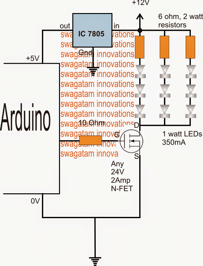
For controlling 9nos of 1 watt LEDs together through an Arduino, the following simple set up may be incorporated through a 12V external supply:

ARDUINOHIGHWATTFLASHER 2

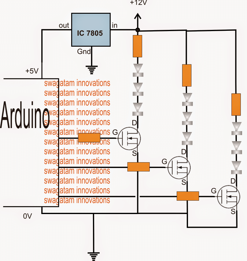
For controlling single LEDs or multiple LEDs from separate Arduino outputs, individual mosfets may be required as given below:

ARDUINOHIGHWATTFLASHER 1 1

The LED resistors may be calculated using the following formula:

R = (U - LEDfwdV)/LED Current

where U is the supply voltage

LEDfwdV is the LED forward operating voltage of the particular series

LED current is the ampere rating specs of the LEDs used

Therefore here U = 12V

LEDfwdV = 3.3V x 3 = 9.9V since 3nos are there in each series and 3.3V being the forward voltage spec of each LED

LED current = 350mA, let's take it 300mA or 0.3Amp to keep things cooler.

Substituting these in the formula:

R = (U - LEDfwdV)/LED Current

= 12 - 9.9/0.3

= 7 ohm

watts may be calculated as

Watts = LEDfwdV x LED current = 9.9 x 0.3 = 2.97 watts or 3 watts

You'll also like:

  • 1.  LED Light Wave Effect Generator Circuit
  • 2.  LED Strip Light Dimmer Controller Circuit
  • 3.  How Crank Flashlights Work
  • 4.  LED Arrow Direction Indicator Circuit
  • 5.  Buck Converter Circuit Using Arduino
  • 6.  Converting Analogue to Digital (Analogue Read Serial) – Arduino Basics

About Swagatam

I am an electronics engineer with over 15 years of hands-on experience. I am passionate about inventing, designing electronic circuits and PCBs, and helping hobbyists bring their projects to life. That is why I founded homemade-circuits.com, a website where I share innovative circuit ideas and tutorials. Have a circuit related question? Leave a comment.... I guarantee a reply!

Previous Post: « How to Make an Industrial Delay Timer Circuit
Next Post: Model Locomotive Infrared Controller Circuit »

Reader Interactions

Comments

  1. El W@?TIN says

    January 5, 2016 at 4:31 am

    what mosfet you are using??? thanks

    Reply

Need Help? Please Leave a Comment! We value your input—Kindly keep it relevant to the above topic! Cancel reply

Your email address will not be published. Required fields are marked *

Primary Sidebar

Subscribe to New Circuit Ideas

Categories

  • Arduino Projects (87)
  • Audio and Amplifier Projects (132)
  • Automation Projects (17)
  • Automobile Electronics (101)
  • Battery Charger Circuits (82)
  • Datasheets and Components (102)
  • Electronics Theory (143)
  • Free Energy (37)
  • Games and Sports Projects (11)
  • Grid and 3-Phase (19)
  • Health related Projects (25)
  • Home Electrical Circuits (12)
  • Indicator Circuits (14)
  • Inverter Circuits (87)
  • Lamps and Lights (142)
  • Meters and Testers (69)
  • Mini Projects (46)
  • Motor Controller (64)
  • Oscillator Circuits (27)
  • Pets and Pests (15)
  • Power Supply Circuits (108)
  • Remote Control Circuits (50)
  • Security and Alarm (64)
  • Sensors and Detectors (100)
  • Solar Controller Circuits (59)
  • Temperature Controllers (42)
  • Timer and Delay Relay (49)
  • Transmitter Circuits (29)
  • Voltage Control and Protection (37)
  • Water Controller (36)

Calculators

  • Battery Back up Time Calculator
  • Capacitance Reactance Calculator
  • IC 555 Astable Calculator
  • IC 555 Monostable Calculator
  • Inductance Calculator
  • LC Resonance Calculator
  • LM317, LM338, LM396 Calculator
  • Ohm’s Law Calculator
  • Phase Angle Phase Shift Calculator
  • Power Factor (PF) Calculator
  • Reactance Calculator
  • Transistor Astable Calculator
  • Transistor base Resistor Calculator
  • Voltage Divider Calculator
  • Wire Current Calculator
  • Zener Diode Calculator
  • Filter Capacitor Calculator
  • Buck Converter Calculator
  • Boost Converter Calculator
  • Solar Panel, Inverter, Battery Calculator
  • Wire Current Calculator
  • SMPS Transformer Calculator
  • IC SG3525, SG3524 Calculator
  • Inverter LC Filter Calculator

People Also Search

555 Circuits | 741 Circuits | LM324 Circuits | LM338 Circuits | 4017 Circuits | Ultrasonic Projects | SMPS Projects | Christmas Projects | MOSFETs | Radio Circuits | Laser Circuits | PIR Projects |

Recent Comments

  • Swagatam on Simple Delay Timer Circuits Explained
  • Swagatam on The Role of Inductor Coil in SMPS
  • Swagatam on 7 Modified Sine Wave Inverter Circuits Explored – 100W to 3kVA
  • Swagatam on 7 Modified Sine Wave Inverter Circuits Explored – 100W to 3kVA
  • Victor on 7 Modified Sine Wave Inverter Circuits Explored – 100W to 3kVA

Company

  • Privacy Policy
  • Cookie Policy
  • About Me
  • Contact
  • Disclaimer
  • Copyright
  • Videos
  • Sitemap

Social Profiles

  • Twitter
  • YouTube
  • Instagram
  • Pinterest
  • My Facebook-Page
  • Quora
  • Stack Exchange
  • Linkedin
  • © 2025 · Swagatam Innovations