The first successful assessment of PID control theory was practically verified in the field of automatic steering systems for ships, way back around the year 1920. After this it was applied in various industrial automatic process controls requiring optimized and accurate manufacturing output specifications. For manufacturing units PID was popularly implemented for achieving precise pneumatic control, and ultimately the PID theory was applied in electronic controllers in modern times.
What is PID Controller
The term PID is the acronym for proportional integral derivative controller, which is a feedback loop mechanism, designed to accurately control various industrial control machineries, and many other similar applications which require critical and automated modulation controls.
In order to implement this, a PID controller continuously monitors the system operation, and calculates the induced error element. It then evaluates this instantaneous error value in the form of difference between the required set-point (SP), and the measured process variable (PV).
With reference to the above, an instantaneous and automatic feedback correction is executed in terms of proportional (P), integral (I), and derivative (D) expressions, and hence the name PID controller.
In simple words a PID controller continuously monitors the working of a given machine system, and keeps correcting its output response depending on the variations caused by external influences, through a specified algorithm. Thus it ensures that the machine always works within the stipulated ideal conditions.
Understanding PID Block Diagram
A PID controller is considered a versatile control system due to its ability to detect and manage 3 control parameters: proportional, integral and derivative, and apply the intended optimal control on the output with extreme accuracy, with reference to these 3 parameters.
The image below shows the block diagram of the PID. We can quickly understand the basic principle of working of a PID by referring to this block diagram.
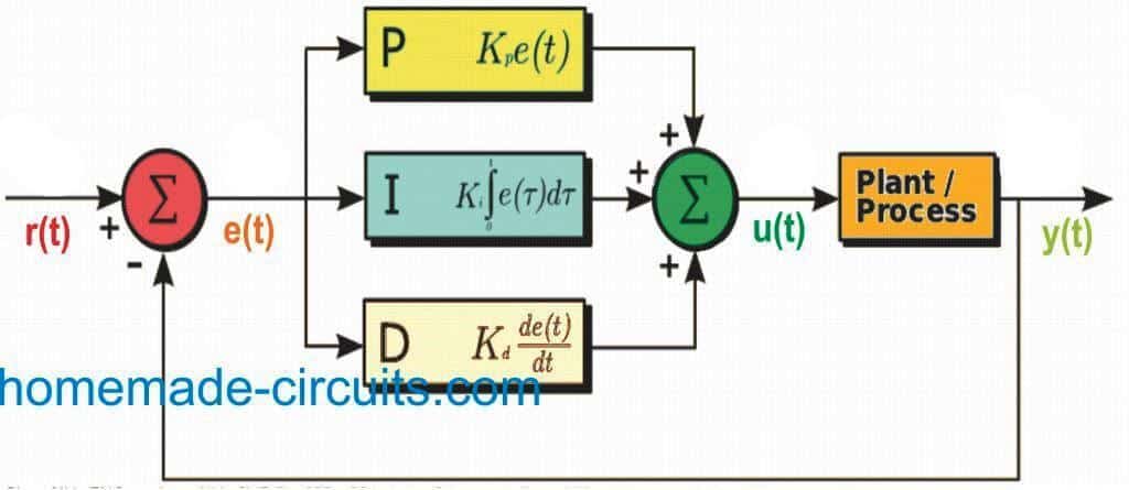
image courtesy: en.wikipedia.org/wiki/File:PID_en.svg
Here we are able to see a set of variables such as e(t) corresponding to the error value, r(t) corresponding to the targeted set point, and y(t) as the measured process variable. The PID controller throughout its operation monitors the error value e(t) by assessing the difference between the intended setpoint r(t) or SP and measured process value y(t) or PV, and consequently executes a feedback correction or optimization using the parameters namely: proportional, integral, and derivative.
The controller continues making an effort to reduce the error effect throughout, by adjusting the control variable u(t) to fresh values based on the analyzed weighted sum of the control terms (p, I, d).
For example, in the operation of a valve control, its opening and closing may be continuously varied by a PID through complex assessments, as explained above.
In the shown system the various terms can be understood as I have explained below:
P- Controller:
The term P is proportional to the instantaneous error values e(t) acquired by assessing the result for SP – PV. In situation when the error value tends to get large, the control output also gets proportionately larger with reference to the gain factor “K”. However in a process requiring compensation such as in temperature control, proportional control solitarily may lead to inaccuracies across the setpoint and the actual process value, since it cannot work satisfactorily without an error feedback to generate the proportional response. Implies that without an error feedback, proper corrective response may not be possible.
I- Controller:
The term I becomes responsible for the previously evaluated values of SP – PV errors, and integrates them during its operational period to create the term I. For instance while the proportional control is being applied if the SP – PV produces some error, the parameter I gets active and attempts to terminate this residual error. This actually happens with a control response triggered due to cumulative value of the error recorded at an earlier time. As soon as this happens the I term stops enhancing any further. This causes the proportional effect to correspondingly minimize as the error factor deceases, although this also gets compensated as the integral effect develops.
D- Controller:
The term D is a most suitable approximation deduced for the evolving trends for the SP – PV error, depending on the instantaneous rate of change of the error factor. If this rate of change enhances rapidly, the feedback control implements more aggressively, and vice versa.
What is PID Tuning
The above discussed parameters may require correct balancing for ensuring optimal control function, and this is achieved through a process called “loop tuning”. The involved tuning constants are denoted as “K” as shown in the following deductions. Each of these constants must be individually derived for a selected application, since the constants strictly depend and vary as per the characteristics and influences of the specific external parameters involved in the loop. These may include the response of the sensors employed for measuring a given parameter, the final throttling element such as a control valve, a possible time elapse in the loop signal and the process itself etc.
It may be acceptable to employ approximated values for the constants at the start of implementation based on the type of application; however this may ultimately require some serious fine tuning and tweaking through practical experimentation, by forcing changes in set points and subsequently observing the response of the system control.
Whether a mathematical model or in practical loop, both can be seen employing a “direct” control action for the specified terms. Meaning when an increase in a positive error is detected, a correspondingly increased positive control is initiated to control the situation for the involved terms summed up.
However this may be required to be reversed in applications where the output parameter may have an oppositely configured characteristic necessitating a reverse corrective measure. Let’s consider the example of a flow loop wherein the valve opening process is specified to operate using 100% and 0% output, but needs to be controlled with a corresponding 0% and 100% output, in this case a reverse corrective control becomes essential. To be more precise consider a water cooling system having a protection feature in which its valve is required to be 100% open during a signal loss. In this case the controller output must be able to change to 0% control in the absence of a signal, so that the valve is able to open at a full 100%, this is termed as “reverse acting” control.
Mathematical Model of the Control Function
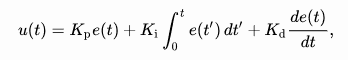
In this mathematical model, all non-negative constants Kp, Ki, and Kd signify coefficients for the proportional, integral, and derivative terms respectively (on some occasions these are also denoted P, I, and D).
Customizing PID Control Terms
From the above discussions we understood that fundamentally PID control system works with three control parameters, however some smaller applications may prefer using a couple of these terms or even a single term out of the three terms.
The customization is done by rendering the unused term to a zero setting, and incorporating the couple of terms PI, PD or single terms such as P or I. Among these, PI controller configuration are more common since the term D is usually prone to noise influences and therefore eliminated in most cases, unless strictly mandatory. Term I is normally included since it ensures the system to achieve the intended optimal target value at the output.


Comments
Good morning Ji.
Nice explained!
Is it compulsory to have a programmable IC in PID based controller cards , which are used in temperature controller for industrial equipment.
For example set point is 185 oC and if machine could not achieve the same in particular time
there will be a Fault output
If temp. fall down at 183 oC after reaching 185 oC there will be Warning output from machine. it is working of machine.
Is it possible to design temperature controller without having programmable IC , with above said function .
Thank you Swagtam Ji.
Thank you Devendar ji,
For controlling temperature with specifications as explained by you can be easily achieved using discrete components, programming may not be required. Industrial systems normally work with many sophisticated parameters which may require extremely sophisticated calculated controlling, a PID becomes essential for such complex control implementation.
An excellent site for aspiring students and entrepreneurs. Keep up the good work.
Thank you Philip.