In this article I have explained 3 popular functions of capacitors and how to use capacitors in electronic circuit by analyzing their appropriate working modes depending on the application need of a given circuit stage
Introduction
Seen those colorful, cylindrical and chocolate shaped parts on a PCB? These may be actually the capacitors of different makes and brands used extensively in electronic circuits. To know more regarding what is a capacitor, just go through the article.
If you are new to electronics and eager to grasp the subject fast, then perhaps you will first have to get familiar with the various components used in electronic circuits.
One of the very important components which finds its place almost in every piece of electronic circuit is the capacitor. Let’s try to understand what is a capacitor?
How Does a Capacitor Function?

Looking at the symbol of a capacitor we see that, it has two plates or poles separated by a space. Practically too, that is what a capacitor is exactly made up of.
Also known as condensers, a capacitor internally consists of two conducting plates separated by an insulator or the dielectric.
According to its working principle, when a voltage (DC) is applied to its pair of conducting plates, an electric field is generated across them.
This field or energy is stored across the plates in the form of charge. The relation between voltage, charge and the capacitance is expressed through the formula:
C = Q/V.
Where C = Capacitance, Q = Charge and V = Voltage.
So it can be clearly understood from the above formula that the potential drop or the voltage across the plates of a capacitor is proportional to the instantaneous charge Q stored in the capacitor. The unit of measurement of capacitance is Farad.
The value of a capacitor (in Farads) depends on the amount of charge it can store in it.
What is a capacitor used for?
The following illustrations will clearly make you understand what is a capacitor used for? In electronic circuits, capacitors are commonly used for the following purposes:
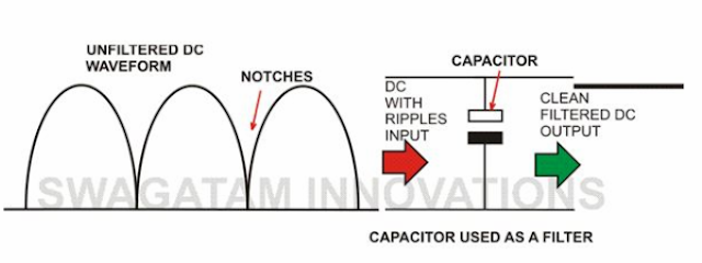
To Filter AC:
A power supply circuit may be rendered useless without a filter capacitor. Even after full wave rectification, the voltage of a power supply may be full of ripples. A filter capacitor smoothes down these ripples and fills up the voltage” notches” or gaps by discharging its internal stored energy. Thus the circuit connected to it is able to receive a clean DC supply voltage.
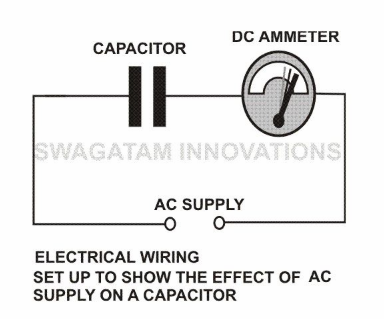
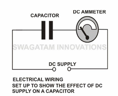
To Block DC:
Another very interesting property of capacitors is to block DC (Direct Current) and allow AC (Alternating Current) to pass through it.
The internal operation of many sophisticated electronic circuits involves the use of frequencies which are in fact small alternating voltages.
But since every circuit requires a DC to be functional, sometimes it becomes very important to block it from entering the restricted areas of the circuit. This is effectively countered using capacitors which allow the frequency part to pass and block the DC.
To Resonate:
A capacitor when conjugated with an inductor will resonate to a particular frequency which is fixed by their values.
In simple words the pair will respond and lock to a particular external applied frequency and will start oscillating at the same frequency itself.
The behavior is well exploited in RF circuits, Transmitters, metal detectors etc.
In general you must have now understood what is a capacitor? But there are still numerous different complicated ways through which a capacitor may be configured. Hopefully you will get to read them in my forth coming articles.

Comments
Please what is the difference in value of 2 pieces of 2000MFD 50v in series first, and second put a diode in between to add up the voltage?
In series it will be 1000uF/100V
I am not sure how a diode in between can add up the voltage, it is not required.
Good day Swag, please how can I prevent sudden outburst discharge which is in seconds of large capacitor when they are charged up but rather make the discharge releases slowly for like 10secs.
Please is there any way around this?
Hi Seun,
You just have to connect a high value resistor such as a 100k across the capacitor terminals to make it discharge slowly.
Thanks Sir, which capacitor is better to filter small dc voltage input, electrolytic or others
Electrolytic are the best according to me.
Between ceramic 104 and polyester, what are the difference. I saw 2 designs for same operation using the two, ceramic was used in one and polyester in the other.
The polyester capacitor is more rugged and resilient than ceramic, that is why polyester caps are used for high voltage applications.
you are clear my mind actually after reading your article i got clear my complete doubt. thanks for such easy understanding post.
James clark @ electrotopic.com
Glad it helped, please keep visiting!
hi I want to make a circuit of 24dc to12dc converter with 5 amper out put by using capasitor, inductor, ic , risistor& relay
Hi, you can try applying this concept:
https://www.homemade-circuits.com/5v-pwm-solar-battery-charger-circuit/
Hi Swagatham,
Please suggest me a circuit which shorts the capacitor terminals after the voltage level goes below certain value. Thanks in advance. Appreciate your help!
-Uday
Hi Uday, you can apply the following concept
https://www.homemade-circuits.com/low-battery-indicator-circuit-using-two/
may you explain more please ?
first I would thank you so much for sharing the useful for all 🙂
I'm not a specialist in this branch but I am a fan .
I would ask you about something please :
I have a hair clipper machine if you know it "dingling"
callinmall.pk/images/detailed/3/Dingling_Rechargeable_RF-609.jpg
it works on rechargeable batteries .
its batteries are almost damaged so it works so slow and empty soon .
So I've tried to let it works directly to the charger without the batteries but I felt the engine couldn't work by itself until I move it by my hand although I raised the voltage !
I think it has to be linked to a capacitor or something like this to work .
what do I have to do to make it works directly to the charger please ?
thanks again so much
try the hardressers charger with your machine, interchange the parameters to confirm.
mmmm today I went to hairdresser , he has 'the same machine but work in both phases (directly to charger and with battery), I focused to the charger , it's : 4.5v , 500mA
my charger is 1000 mA and using 6-7 Volts
with 4.5 volts the machine never work even with 6-7 volts it works so so slow with my charger !
as already mentioned in the previous comment raising the voltage could damage your machine, rather the current must be raised at constant voltage (3V)
try a regulated 3V, 2amp power supply, make sure the voltage is not above 3V.
I've already use the the charger multi-voltages which its current is 1000 mA !
because the charger of the machine is lost .
the machine was working good with 2 batteries (3 volts) .
but now it doesn't although I raise the voltage to 6-7 volts with this charger 1000 mA !
what is the problem possible here please ??
you are welcome!
The problem can be rectified by using a charger with higher amps, or simply procure a Dc power supply rated at the machine's voltage requirement and having a much higher amps capacity, higher amps will not do any harm, just make sure the voltage rating is never exceeded beyond the machine specs.