An ultrasonic burglar alarm circuit is an electronic device which transmits ultrasonic waves to detect the movement of an intruding person. The ultrasonic waves hit the intruder and the reflected waves are picked up by the circuit. This reflected wave is used to activate a loud alarm which alerts the owner about the presence of an intruder or a potential burglar.
In our ultrasonic burglar alarm circuit, the versatile LM567 phase-locked loop IC is used.
The main technical specifications of the IC are given below.
- Supply Voltage Range 3.5 V to 8.5 V
- Input Voltage Range 20 mV RMS to VCC (+0.5)
- Input Frequency 1 Hz to 500 kHz
- Output Current Max. 15 mA
For more information about the IC you can refer to the following post:
In our present ultrasonic burglar alarm design, the IC LM567 implements two functions together.
It works like a tone-decoder circuit that switches ON the output in response to a specific tone frequency linked with the LM567 at pin#3.
Additionally, the LM567 functions as a tone transmitter, producing the exact frequency tone from pin#5 that the receiver stage is intended to receive and detect.
Meaning, the pin#5 generates a tone with a specific frequency, and when this same frequency is supplied back to its pin#3, then the IC switches ON its output pin#8. If any other frequency is detected at pin#3 the IC does not respond and its output remains inactive.
Therefore, it implies that the frequency set to be generated from pin#5 must be exactly detected at pin#3 for the output to become active. If pin#5 and pin#3 frequencies don't match then the output will never switch ON.
The sensor stage of the circuit could be built with just a couple of external transistors and a few other parts. The transmitter section of the circuit uses the piezo speaker to transmit a high frequency audio signal.
The reflected tone signal is detected by the receiver's pickup, which is an electret microphone device, and is then sent to transistor Q1 for amplification. The signal is then transferred to the input of the LM567 after being amplified.
As depicted in the diagram, the piezo speaker and microphone units are placed 3 to 6 inches apart, facing towards the target which can be a possible intruder.
The circuit switches ON the output alarm device whenever something is moved in front of the microphone and speaker which reflects enough of the signal back to the microphone. The circuit may be configured to detect items from a few inches to over a meter away.
Circuit Description
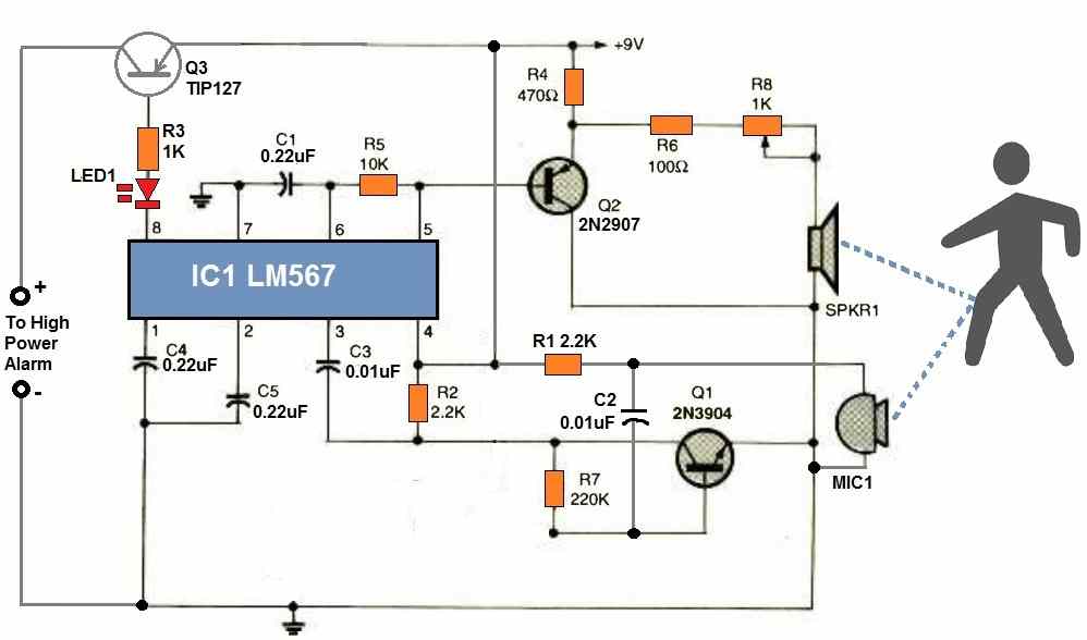
Referring to the above ultrasonic burglar alarm circuit diagram, we can understand the working of the circuit with the following explanation
C1 and R5 determine the internal oscillator frequency of the LM567. It doesn't matter what the operating frequency range is as long as it is between 14 and 20 kHz.
The electret microphone's sensitivity will be diminished and its operational range will deteriorate if the frequency is set too high. The circuit can operate at much lower frequencies if you don't mind hearing to the continuously emitted high-frequency sound.
At pin#5, the internal oscillator of the LM567 generates a squarewave output. Q2 operates as an emitter follower to isolate this signal from the LM567 and feeds it to the piezo speaker.
R8 controls the output volume of the speaker. The common-emitter amplifier transistor Q1 is used to boost the reflected tone signal to a magnitude at which LM567's input circuitry can detect and latch on.
How to Setup
Setting up and adjusting the circuit is simple.
- Choose the desired type and size of anything you wish to detect and place it directly in front of the speaker and microphone, until the output alarm starts sounding.
- Now adjust R8 to tweak the range of the detection. The range of operation is primarily determined by the type of item chosen as a reflector. For example any object with a flat surface will be detected better than objects having cylindrical surface.
This circuit is great for electronics hobbyists and researchers. By substituting R5 with a 20 Kohm potentiometer, the operating frequency could be adjusted. C1's value could also be altered. Smaller values of either component might reduce the operating frequency, whereas larger ones will help to increase it.
Calculating the Operational Frequency
As explained in the previous, the ideal frequency for transmission and detection can be at around 14 kHz. This frequency is determined by C1 and R5.
The formula for calculating this frequency is as given below:
fo = 1 / (1.1 × R1 × C1)
Here, R1 should be in Ohms, and C1 should be Farads. The frequency will then be in Hertz.
Parts List
- RESISTORS
- (All resistors are 1/4 -watt, 5% units unless otherwise noted.)
- R1, R2 - 2.2K
- R3 - 1K
- R1 - 470 ohm
- R5 - 10K
- R6 - 100 ohm
- R7 - 220K
- R8 - 1K potentiometer
- CAPACITORS
- C1 - 0.22 uF, ceramic disc
- C2, C3 - 0.01 uF, ceramic disc
- C4, C5 - 0.22 uF ceramic disc
- SEMICONDUCTORS
- IC1 - LM567 tone -decoder, integrated circuit
- Q1 - 2N3904 NPN silicon transistor
- Q2 - 2N2907 PNP silicon transistor
- Q3 - TIP127 PNP Darlington Transistor
- LED1 - Light-emitting diode, any type or color
- Miscellaneous
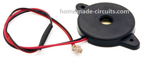
- Piezo Buzzer
- Electret MIC


Questions & Answers
Hi Mr. Swagatam;
I hear about the some burglar circuits can distinguish the human and animals and so it can be sensitive for only human motion. Could you please share your opinion about the matter?
Hi Suat,
I am not sure how the sensor can differentiate humans from animals, because both generate similar kind of IR radiation. I guess they may be differentiating humans from animals by checking the body structure, which might be programmed in their circuits.
Dear Sir Swagatam
Hello. Hope you are fine and healthy.
According to the symbols of the capacitors on the diagram, I asked for the electrolytic capacitors for C2 = 0.01 and C3 = 0.02 uf. A few of the sellers however told me that they had not seen these values of electrolytic capacitors yet. I got ceramic ones for C2 and C3 instead, and after assembling the circuit and testing it, while I was writing to you, I noticed that all capacitors have been written as ceramic capacitors on the parts list. Substituting 3 other capacitors with ceramic ones after retesting the circuit did not also cause the circuit to work.
I assembled the circuit and connected it to a 5 Volts power supply and I heard nothing but a continuous whistle sound as you would see on the video test file that I have sent to you. Moreover, neither rotating the potentiometer nor substituting transistors and IC with new ones or even substituting R7 with a 22k resistor that had been written on the parts list, resulted in the circuit working as it has been described in the circuit description. Please be informed that I always test the components before mounting them or getting them together.
Wish you all the best and God bless you
Sincerely yours
Ali
Dear Ali,
I asked original contributor, he said that he had taken the circuit design from an old popular electronics magazine Poptronics USA. These guys always test the circuit and then publish it in the magazine. So the circuit cannot be wrong.
You have assembled the parts on a breadboard, I hope there are no loose connections.
However I cannot see any Electret MIC in your prototype images which you sent me. Are you sure you connected the MIC?
OK, yes, I can see the MIC in the video you sent.
Please place the MIC and the piezo buzzer 6 inches apart or little more closer and check again by moving a rigid flat object in front of the piezo/MIC.
Dear Sir Swagatam
The Mic and the Piezo buzzer are exactly 15 cm apart in the video.
I took these 2 elements closer and farther a few times; and moved my hand in front of them, from different distances, while they were 2 meters far from the opposite wall and the feedback was the whistling sound as before. I assure you of no loose connection in any component. Only, since the piezo wires were thin, I soldered them to 0.7 mm wire in order to be fixed in the breadboard holes.
Thanks a lot for your reply
Sincerely yours
Ali
Thank you Ali, for the detailed information,
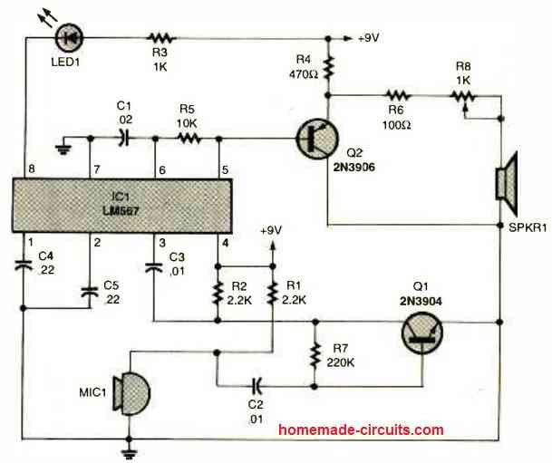
I found the original circuit which you can check in the following link. Instead of an alarm an LED is used here. Please check if you can find any difference in this diagram and amend your circuit accordingly and check the response:
Dear Sir Swagatam
I compared the two circuit diagrams; they are the same, I removed the TIP127 transistor according to the recent circuit diagram. It still does not work. If I have enough time to mount the components on a PCB I will share you the results.
Thanks for all your endeavor and favor
Best wishes
Ali
Thank you again Dear Ali, for your kind cooperation.
I am sorry to hear the original diagram from the popular magazine is having problems.
Hope something changes when assembled on a PCB.
I hope so dear Swagatam and thank you again who are so a good man.
Dear Sir Swagatam
Good morning. Thanks a lot for the original circuit diagram. OK, this is the least I will do for your favor.
Best regards
Ali
Thank you Dear Ali!
Sir engineer Swagatam
Hello. Thank you very much for so soon reply.
All the best
Max
No problem max, All the best to you!
Sir engineer Swagatam
Hello. I am new to your site which is so interesting, and I want to try the circuit. Would you kindly tell me if the SPKR1 on the diagram is the same as the Piezo buzzer on the parts list?
All the best
Max
Thank you Max, Glad you liked the site!
Yes SPKR1 is a piezo buzzer as mentioned in the parts list, used for emitting high frequency untrasonic waves.
Dear Sir Swagatam
Hello. I see different values for C1 and R7 on the circuit diagram and parts list.
Would you please tell me which one is correct
Thanks a lot
Wish you all the best
Thank you so much Ali, for pointing out the mistake.
According to me the diagram is correct. The parts list will need to be updated according to the circuit diagram.
However, for C1, if 0.22uF does not work, then you can try 0.022uF.
All the best to you.
Dear Sir Swagatam
Hello. Hope you are fine and healthy. Thank you for publishing this interesting circuit.
I am going to do this project and share the results with you.
Would you please answer my questions:
1. should the Mic and Speaker be placed face to face?
2. what could be the utmost distance of these 2 components from each other?
3. Am I allowed to use an eight-ohm sp. of any watts for SPKR1?
Best regards
Ali
Thank you Ali,
Sure, you can try this circuit and share your results here. However this circuit was not designed me, it was designed by some other author, but I believe this will work.
1) MIC and speaker should be paced parallel to each other, both facing towards the target.
2) Distance can be around 6 inches apart.
3) Yes 8 ohm speaker will do, but 8 ohms is the preferred wattage.