In this article I have explained a simple two step IC 555 timer circuit which can be used for sequentially operating any specified industrial mechanism system, in this application it's used for operating a pressurized pneumatic ball throwing arm. The idea was requested by Mr. Ray Strong.
Technical Specifications
So glad I found this site, might be my new Favorite. I'm an amateur here who's racked his brain enough already.
Hoping you can help me out. What I need is an "on delay/true off delay timer" as detailed here--> https://drive.google.com/open?id=0B8cU3NynJy7kekE4bXIxUFBORXM .
The signal going to the delay timer will be from a "pulsepause timer" and I would like to just have the delay timer delay that pulsepause signal before replicating it a half second later to another component.
Basically I need it to produce the same signal for the same duration but just delayed a fraction of a second.
Is there something cheap out there that will do this for under $30 or could you provide me with a schematic.
I plan on using the supply voltage to supply the three things that would need it (pulse/pause input,pulse/pause relay input and the delay timer relay input).
I suppose this could all be incorporated on one circuit board but I already have the pulse/pause timer and am just looking to add a second delayed signal.
But to add to that I would like the "T2" delay (shown in the above posted link) to be adjustable from about .1 to 1 second.
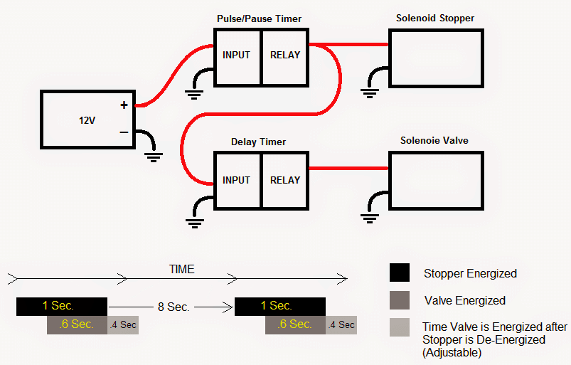
What I am using it for is a pneumatic ball throwing arm. The pulse/pause timer output will be used to trigger a latch to hold/lock the arm and also to trigger the start of the delay timer at the same time.
At the end of the "on" delay of the delay timer it will trigger the pneumatic valve to open, pressurizing the cylinder (which is still held by the latch).
At the end of the pulse/pause time (when pulse pause relay is opened), the latch will release allowing the cylinder to extend at a higher rate than would be possible without it being previously pressurized. Now the next part is where I want it adjustable.
I need the time the relay on the delay timer is is closed to be adjustable so I can adjust how long the pneumatic valve is opened. Another spec would be that the "on" delay of the delay timer should be about .25 to .5 seconds.
Sorry if this is confusing. I'll post a sketch today to give you a visual.
Thanks!
Here's the sketch:
The Design
The proposed two step timer for operating a pressurized pneumatic arm can be studied through the following circuit design.
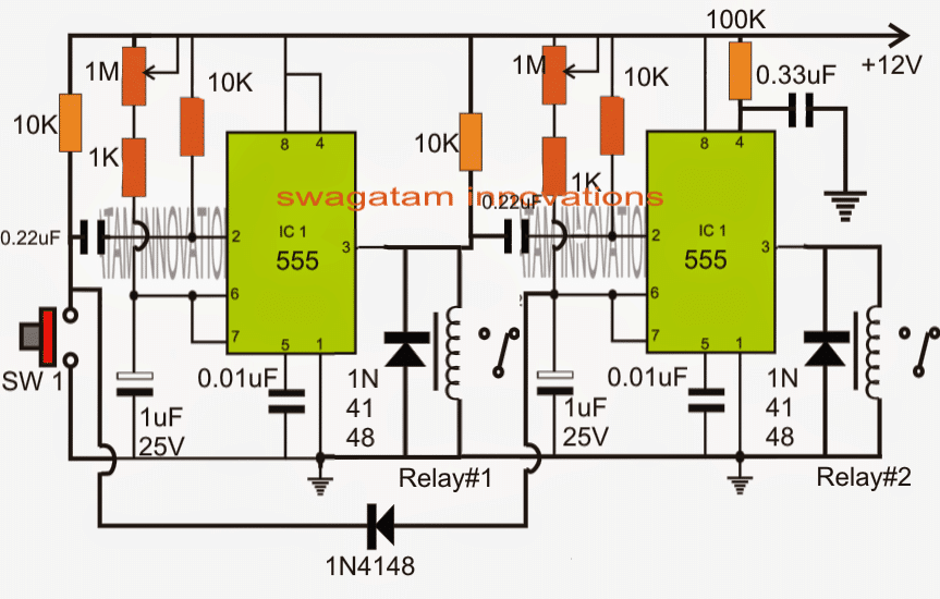
The circuit is designed such that it includes both the timer stages (t1 and t2) together, and the external pause/pulse mechanism can be eliminated.
Basically two IC 555 stages are used here which are coupled together in series, both of these are configured as monostable operators.
When power is switched ON, the pin#3 of the left IC is held at a low logic which triggers pin#2 of the right hand side IC to ground, however pin#3 of the right side IC is unable to go high and respond to this trigger because its pin#4 simultaneously goes through a momentary disabling (resetting) via the 100k and the 0.33uF capacitor.
Thus in the meantime its pin#2 capacitor 0.22uF charges and keeps things frozen for the moment with no reaction on the connected relay.
SW1 forms the trigger initiator, as soon as SW1 is pushed, pin#2 of the left IC receives a ground signal and pulls pin#3 of the IC high, activating relay#1....the solenoid stopper now gets energized through this relay.
The above action allows the right side IC pin#2 capacitor to get discharged via the two 10K resistors across its ends and allows this IC to attain a standby position.
The left side IC now counts depending upon the setting of its 1M preset and the 1uF/25V capacitor.
Once the time elapses, pin#3 of the left IC reverts to logic zero, causing a momentary negative pulse to pin#2 of the right side IC. Relay#1 deactivates, de-energizing the stopper solenoid connected to it.
This prompts a sequential toggling of the right side relay whose pin#3 now becomes high and which in turn switches ON the connected relay#2. The solenoid valve instantly get energized at this instance via relay#2.
The IC now begins counting the delay period as set by the RC components across its pin#6/2.
Once the timing of the right side IC too elapses, its pin#3 goes low deactivating relay#2, and resetting the timers to its original condition.
The diode linking the two ICs makes sure that while the right IC is counting, any triggering of SW1 only helps to prolong the counting of the IC due to the resetting (discharging) of its timing capacitor at pin6/2.
Feedback from Mr. Ray Strong
Thank you so much for your help and prompt response, however in reading your explanation of the timer circuit for pneumatics I'm not sure that it operates to the specs I need.
You mentioned that the external pulse/pause timer can be eliminated but that is the circuit that will be triggering the cycle every 8-10 seconds. As I mentioned you could incorporate that timed trigger into the the delay circuit but I don't see that you did that here. Y
ou mention when SW1 is pressed that relay #1 is activated and the solenoid stopper gets energized. That's fine but for my purposes I would have the voltage from pulse/pause circuit be the trigger in place of your SW1. Basically I need to have the whole thing cycling every 8-10 seconds to throw a pitch every 8-10 seconds. So a push button isn't the best for me. For my sake I'd prefer to use the external pulse/pause timer for now as I can use its output to control other components of my mechanism.
Also you mention from my understanding that when the stopper solenoid is de-energized the valve is then energized.
This is not what I was expecting. What I needed was for the valve to energize for about .5 seconds before the stopper de-energizes and then stay energized for an adjustable time period after the stopper de energizes. Basically I need what my sketch illustrates.
Forgive me if these specs have been met in your design, but I didn't understand how your explanation of the circuit met my needs. Could you possibly have a second look to see that these timing needs are met and if possible could you list the steps also with a more straight forward explanation, like just the steps the cycle would go through.
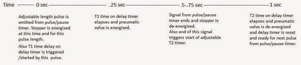
Here is a better laid out description.
If you have any question before you get into the design feel free to let me know.
As per the above discussion I have made the appropriate changes in the design, the finalized layout may be witnessed below, and understood with the adjoining explanation:
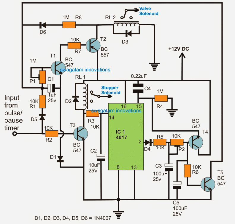
Positive supply is applied to the pin#16 rail of the IC 4017, when switched ON, C4 resets the IC causing pin#2 to produce a zero logic at the base of T3, and the entire circuit waits in a standby condition.
When a positive pulse is applied to the base of T2 from the external pulse/pause timer, T3 instantly conducts and actuates RL1 switching ON the "stopper solenoid".
In the meantime C1/P1 along with T1/T2 which forms a short delay ON timer circuit (t1) also responds to the external trigger and latches via R8/D6 and in the process activates RL2 after some delay as determined by the setting of P1/C1.
RL2 now actuates the pneumatic valve.
After a predetermined delay, the pause pulse timer switches OFF, turning OFF T3 and RL1 along with the stopper solenoid.
As soon as T3 switches OFF, pin14 of the IC4017 receives a positive trigger pulse via the relay coil and R3.
The above trigger forces a sequential high logic to jump from pin#3 (not shown) to pin#2 of the IC.
Another "delay ON timer" (t2) connected across pin#2 of the IC now begins counting, and after some delay T4 is switched ON, along with T5.
T4 sends a resetting pulse to pin#15 of the IC, while T5 conducts and makes sure that the T1/T2 latch breaks so that RL2 is deactivated along with the valve solenoid.
The above actions completely resets the entire circuit until the next input from the pulse/pause timer is applied.


Comments
I have a need similar to this but here are the details. I have a motor turning a crank clockwise for x amount of time (selectable 10-30sec). Then delay 10 seconds. Then Turn the motor counterclockwise for x amount of time (selectable 10-30sec). Then delay 10 seconds and repeat until we flip the switch off. It would be great to have a digital cycle counter which triggers once it has run the counterclockwise cycle and keeps cycle count even when we turn off the unit so it will keep adding to the count the next time we run it.
The load will be around 70-80amps so planning on using 100-120amp relays but don’t know if I should use single or double throw relays for this.
Your help is greatly appreciated.
Reverse forward with delay can be designed, but keeping the cycle count intact once the power is switched off looks difficult, unless a battery is used for retaining the memory
Yes. we will have a 12v 20ah battery attached to run the unit but I guess we may need to have a bypass wire or a constant feed on the circuit to the counter prior to the on/off switch.
OK, for operating the motor in reverse forward manner, we can use the following concept:
https://www.homemade-circuits.com/motor-reverse-forward-2/
The switch S1 in the above diagram can be replaced with a relay contact.
This relay contact can be controlled by the following timer circuit:
https://www.homemade-circuits.com/wp-content/uploads/2021/06/motor-timer-compressed.jpg
The above is just a basic concept, you may have to upgrade the transistors to MOSFETs for handling high amps.
If you want to use a relay for the reverse forward, then the first circuit can be avoided, and the timer relay can be replaced with a DPDT relay.
But even with these arrangements I am not able to figure out how exactly the motor halting position can be remembered by the circuit, even with a battery
Thanks for the info. the motor position doesn’t need to be remembered. Just the number of cycles the motor goes in forward and reverse. So on the counter, it will be on the whole time while the rest of the circuit is turned on and off by a switch. Hope that helps. Yes we can use mosfets if needed but 100A or 120A relays should be just as easy to attain, if you think it will be an easier solution. If using very high power mosfets will simplify the circuit and wiring, we can go that route. Look forward to your response and schematic.
Here’s a approximate design as per your requirements:
If the IC 555 output is adjusted to provide 10 seconds ON, OFF clocks, this will give 30 seconds ON time for the reverse forward motions, and a gap of 10 seconds OFF in between.
The 30 seconds ON time can be altered by disconnecting one or two diode inputs from the bases of the respective transistors.
The relay contacts must be rated at 100 amps
….the upper relay is DPDT, the lower relay is SPDT
Good day.
Thank you very much for your help.
I'll wait for the design.
Greetings.
I have posted it here: please check it out:
https://www.homemade-circuits.com/2015/08/classroom-debate-timer-circuit.html
Sorry but that still is different. Here is a better laid out description.
https://drive.google.com/open?id=0B8cU3NynJy7kNWRHS0hwOUt1STg
If you have any question before you get into the design feel free to let me know.
I have updated it in the above article….
OK, that's great, I am working on it and will try to finish it soon….
Here is a video of the remote switch and the timer I have so far.
https://drive.google.com/open?id=0B8cU3NynJy7kb3dnb0otNFdhTkU
Here is some more info of my plan.
https://drive.google.com/open?id=0B8cU3NynJy7kWVdiWlhWU1pwem8
OK thanks, now it looks much better…. but a little complex than what I interpreted earlier, it's feasible though….I'll try to update the finalized design soon and let you know.
Good day, Mr. Swagatam
I'm trying to make a visual device to be used in debates among students. So I came with this idea: two coloured bulbs, one blue one red. The blue one is turned ON 5 minutes while the participant is talking, after this time is automatically OFF and the red one is turned ON 5 seconds, to indicate the end of speech time and the other participant can be prepared. Then, 5 seconds after, the red bulb is turned OFF and the blue one is ON again. This is a permanent loop after is connected to the power outlet (120v). I think that a visual device its less disturbing and distracting, and thats why i avoiding the use of alarms or buzzers.
I don't know if this project is simple. I know how to do basic soldering but i'm don't know nothing about electronics. It's a small countryside school, so they don't have anyone who knows about electronics and i'm doing some volunteer job. I'll we be glad if you can help me with this and i'm sure this will be really useful in the student meetings.
Thank you very much in advance and sorry if i do some mistakes in my writing.
Greetings from Colombia.
OK, I'll redesign it and present it soon…however your earlier explanation was much easier to understand (the t1..t2 explanation), I'll put it in a step wise manner just to eliminate confusions:
the positive pulse from the pause/pulse timer triggers a "delay ON timer" circuit….this timer circuit waits (as per the set delay period) and generates a positive pulse at its output after the set delay has elapsed.
the above positive from the delay timer activates the solenoid stopper, and also simultaneously triggers the next "delay OFF timer", which in turn immediately activates the solenoid valve and keeps it switched ON for a time period as set for the second delay OFF timer.
please confirm the above so that I can produce it in the form a new design.
Thank you so much for your help and prompt response, however in reading your explanation of the timer circuit for pneumatics I'm not sure that it operates to the specs I need. You mentioned that the external pulse/pause timer can be eliminated but that is the circuit that will be triggering the cycle every 8-10 seconds. As I mentioned you could incorporate that timed trigger into the the delay circuit but I don't see that you did that here. You mention when SW1 is pressed that relay #1 is activated and the solenoid stopper gets energized. That's fine but for my purposes I would have the voltage from pulse/pause circuit be the trigger in place of your SW1. Basically I need to have the whole thing cycling every 8-10 seconds to throw a pitch every 8-10 seconds. So a push button isn't the best for me. For my sake I'd prefer to use the external pulse/pause timer for now as I can use its output to control other components of my mechanism.
Also you mention from my understanding that when the stopper solenoid is de-energized the valve is then energized. This is not what I was expecting. What I needed was for the valve to energize for about .5 seconds before the stopper de-energizes and then stay energized for an adjustable time period after the stopper de energizes. Basically I need what my sketch illustrates. Forgive me if these specs have been met in your design, but I didn't understand how your explanation of the circuit met my needs. Could you possibly have a second look to see that these timing needs are met and if possible could you list the steps also with a more straight forward explanation, like just the steps the cycle would go through. Thanks again.
Good day, Mr. Animales,
Thanks for exptressing your request, I'll try to post the design soon for your reference.