• Skip to main content
  • Skip to primary sidebar

Homemade Circuit Projects

Need circuit help? Post them in the comments! I've answered over 50,000!

Blog | Categories | About | Contact | Calculators-online
You are here: Home / Timer and Delay Relay / How to Make a Classroom Debate Timer Circuit

How to Make a Classroom Debate Timer Circuit

Last Updated on July 6, 2019 by Swagatam 6 Comments

In this post I have explained how to make a simple classroom debate timer circuit which can be used to illuminate two sequentially toggling lamps to indicate the start and finish of the lecture time delivered by the respective members in the class. The idea was requested by Animale.

Technical Specifications

I'm trying to make a visual device to be used in debates among students. So I came with this idea: two colored bulbs, one blue one red.

The blue one is turned ON 5 minutes while the participant is talking, after this time is automatically OFF and the red one is turned ON 5 seconds, to indicate the end of speech time and the other participant can be prepared.

Then, 5 seconds after, the red bulb is turned OFF and the blue one is ON again. This is a permanent loop after is connected to the power outlet (120v).

I think that a visual device its less disturbing and distracting, and that's why i avoiding the use of alarms or buzzers.

I don't know if this project is simple. I know how to do basic soldering but i'm don't know nothing about electronics.

It's a small countryside school, so they don't have anyone who knows about electronics and i'm doing some volunteer job.

I'll we be glad if you can help me with this and i'm sure this will be really useful in the student meetings.

Thank you very much in advance and sorry if i do some mistakes in my writing.

Greetings from Colombia.


classroom debate timer


How The Circuit is Designed

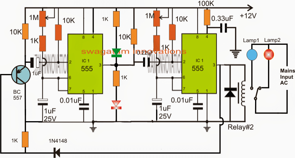
The above request for a classroom debate timer circuit can be implemented with the help of the shown design.

The circuit is basically made by interconnecting two IC 555 monostable stages, which conduct in sequence as per the set predetermined delays, once the circuit is powered.

The delay lengths is adjustable and can be set by appropriately by adjusting the respective 1M pots, and also the respective 1uF/25V capacitors which may be increased for achieving higher delay responses from the ICs.

When power is switched ON, the left IC activates by issuing a high logic at its pin#3 owing to the instantaneous grounding of its pin#2 via the PNP transistor.

While the pin#3 of the left IC remains ON, this IC counts the timing, and in the meantime the right hand side IC stays dormant with its pin#3 at logic zero. The connected relay also stays switched OFF and in the course connects the N/C contact lamp with the mains, the relevant lamp is illuminated.

Once the set time is elapsed, the left IC's pin#3 goes low and in the process grounds the right side IC's pin#2 to ground. The right side IC now switches ON allowing its pin#3 to go high.

The above sequence turns ON the relay which in turn switches OFF the erarlier lamp and toggles the second lamp connected across its N/O contact.

The left IC now begins counting, while this IC counts, the high from its pin#3 switches OFF the PNP
enabling the left IC's 0.22uF capacitor at its pin#2 to get discharged.

After the set time is elapsed, its pin#3 goes low, the relay deactivates flipping the lamp illumination, this also switches ON the PNP grounding the pin#2 of the left IC via the 0.22uF capacitor....the process now loops up and keeps cycling.


You'll also like:

  • 1.  Digital Clock Activated Water Level Controller Circuit
  • 2.  Digital Clock Synchronized Programmable Timer Circuit
  • 3.  10 Best Timer Circuit Diagrams using IC 555
  • 4.  Delay based Motor Speed Controller Circuit – Timer Controlled
  • 5.  1 to 10 minutes Timer Circuit Diagram
  • 6.  Thermostat Delay Relay Timer Circuit

About Swagatam

I am an electronics engineer with over 15 years of hands-on experience. I am passionate about inventing, designing electronic circuits and PCBs, and helping hobbyists bring their projects to life. That is why I founded homemade-circuits.com, a website where I share innovative circuit ideas and tutorials. Have a circuit related question? Leave a comment.... I guarantee a reply!

Previous Post: « No Load Detector and Cut-off Circuit for Inverters
Next Post: Remote Controlled ATS Circuit – Wireless Grid/Generator Changeover »

Reader Interactions

Comments

  1. Animales says

    August 26, 2015 at 7:41 pm

    Good day, Mr. Swagatam

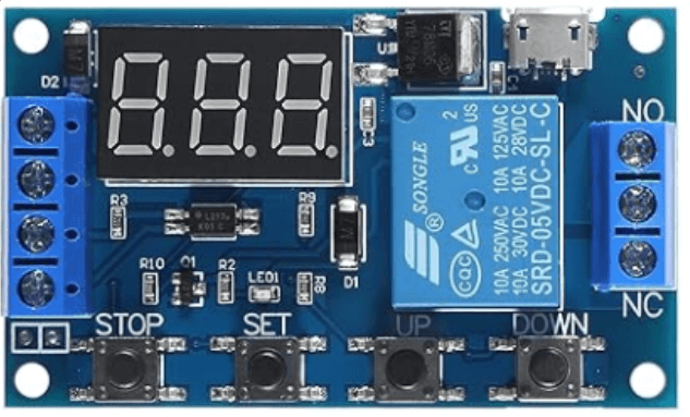
    I got a final question, ¿what kind of relay, the one connected to the lamps and the AC input, can i use?

    Again, thank you very much.

    Have a nice day.

    Reply
    • Swagatam says

      August 27, 2015 at 7:22 am

      Good day Animales, you can use a relay that's shown at the end of this article:

      https://www.homemade-circuits.com/2012/01/how-to-understand-and-use-relay-in.html

      Reply
  2. Animales says

    August 13, 2015 at 10:10 pm

    Greetings, Mr. Swagatam.

    Thanks again for your help. I have some question about the circuit. ¿What kind of diodes are the ones next to the IC in the left? ¿Are they LED's? and the diode next to the relay, ¿Same as the 1N4148?.

    Have a good day.

    Reply
    • Swagatam says

      August 14, 2015 at 9:11 am

      Thanks Animales, you can use 1N4007 for the two diodes shown in black….the red and the green parts are the LEDs 5mm/20mA type

      Reply
  3. Animales says

    August 6, 2015 at 5:40 pm

    Good day, Mr. Swagatam

    Thank you very much, i'm very happy with your help.
    Soon I'll post the result of this project.

    Really thankful.

    Reply
    • Swagatam says

      August 7, 2015 at 9:15 am

      You are most welcome Animales!

      Reply

Need Help? Please Leave a Comment! We value your input—Kindly keep it relevant to the above topic! Cancel reply

Your email address will not be published. Required fields are marked *

Primary Sidebar

Subscribe to New Circuit Ideas

Categories

  • Arduino Projects (87)
  • Audio and Amplifier Projects (132)
  • Automation Projects (17)
  • Automobile Electronics (101)
  • Battery Charger Circuits (82)
  • Datasheets and Components (103)
  • Electronics Theory (143)
  • Free Energy (37)
  • Games and Sports Projects (11)
  • Grid and 3-Phase (19)
  • Health related Projects (25)
  • Home Electrical Circuits (12)
  • Indicator Circuits (14)
  • Inverter Circuits (87)
  • Lamps and Lights (142)
  • Meters and Testers (69)
  • Mini Projects (46)
  • Motor Controller (64)
  • Oscillator Circuits (27)
  • Pets and Pests (15)
  • Power Supply Circuits (108)
  • Remote Control Circuits (50)
  • Security and Alarm (64)
  • Sensors and Detectors (101)
  • Solar Controller Circuits (59)
  • Temperature Controllers (42)
  • Timer and Delay Relay (49)
  • Transmitter Circuits (29)
  • Voltage Control and Protection (37)
  • Water Controller (36)

Calculators

  • Battery Back up Time Calculator
  • Capacitance Reactance Calculator
  • IC 555 Astable Calculator
  • IC 555 Monostable Calculator
  • Inductance Calculator
  • LC Resonance Calculator
  • LM317, LM338, LM396 Calculator
  • Ohm’s Law Calculator
  • Phase Angle Phase Shift Calculator
  • Power Factor (PF) Calculator
  • Reactance Calculator
  • Transistor Astable Calculator
  • Transistor base Resistor Calculator
  • Voltage Divider Calculator
  • Wire Current Calculator
  • Zener Diode Calculator
  • Filter Capacitor Calculator
  • Buck Converter Calculator
  • Boost Converter Calculator
  • Solar Panel, Inverter, Battery Calculator
  • Wire Current Calculator
  • SMPS Transformer Calculator
  • IC SG3525, SG3524 Calculator
  • Inverter LC Filter Calculator

People Also Search

555 Circuits | 741 Circuits | LM324 Circuits | LM338 Circuits | 4017 Circuits | Ultrasonic Projects | SMPS Projects | Christmas Projects | MOSFETs | Radio Circuits | Laser Circuits | PIR Projects |

Recent Comments

  • Swagatam on Best Electronic Circuit Projects
  • TOMMY on Best Electronic Circuit Projects
  • Swagatam on Inverter Circuit with Feedback Control
  • Jerry Adeosun on Inverter Circuit with Feedback Control
  • Swagatam on Contact

Company

  • Privacy Policy
  • Cookie Policy
  • About Me
  • Contact
  • Disclaimer
  • Copyright
  • Videos
  • Sitemap

Social Profiles

  • Twitter
  • YouTube
  • Instagram
  • Pinterest
  • My Facebook-Page
  • Quora
  • Stack Exchange
  • Linkedin
  • © 2025 · Swagatam Innovations