In this post I am going to explain clipper and clamper circuits. The clipper and clamper are called wave shaping circuits because they convert the incoming signal wave to another kind of useful wave.
They are used widely in power supplies, filter circuits, RF transmitters / receivers, voltage suppressors, audio amplifiers and the list goes on.
Clipper Circuit:
What is a clipper circuit?
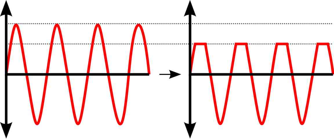
Clipper circuit is a circuit arrangement with diodes and other passive components that prevent electrical signals exceeding a preset voltage level at its output.
When the input exceeds the threshold for which the clipper circuit is designed for, the excess spike voltage is simply clipped or sliced off from the rest of the waveform.
A point to be noted is that only the excess amplitude is clipped off and the rest of the waveform is unaffected. Clipper circuits are often labeled as protection circuits.
Classification of clipper circuit:
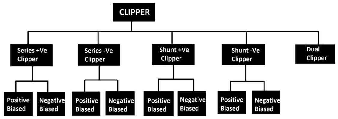
The above block diagram illustrates different types of diode based clippers. There are two main types of clipper circuits and those are series clipper and shunt clipper and the rest of them are derived from these two types.
- A clipper circuit is classified as a series when the diode is in series with load.
- A clipper circuit is classified as shunt when the diode is in parallel with the load.
- A clipper circuit is said to be biased when we apply a voltage to the clipper circuit to control the level of clipping at the output.
- Polarity of the bias determines whether the clipper is positively biased or negatively biased.
- Dual clipper circuit is a circuit arrangement using two diodes where both the half cycles get clipped and they can be biased too.
Now let’s explore each of the clipper circuits mentioned in the block diagram.
Series Positive Clipper:
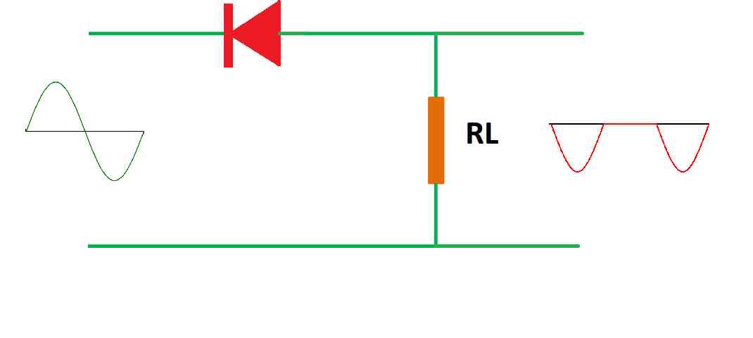
Series positive clipper consists of a diode and a load resistor RL, the positive cycles of the signal are clipped off and negative cycles are passed at the output unaffected.
When the diode encounters a positive signal at the cathode, the diode is reverse biased and no signal is passed to the output.
When the diode encounters a negative signal at the cathode terminal, the diode is forward biased and this signal is passed to the output unaffected.
The above circuit is essentially a half-wave rectifier and it is the most simple clipper circuit.
Series negative clipper:
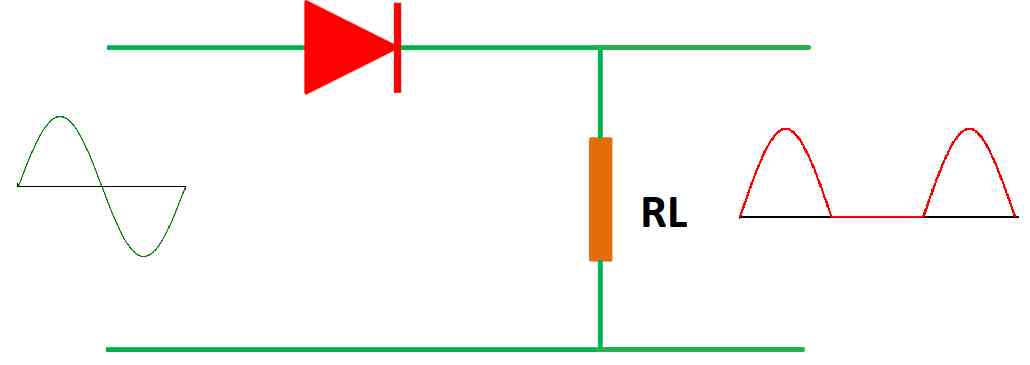
Series negative clipper circuit clips off negative cycles of input signal. The arrangement of this circuit is the same as the previous one except the diode’s position is reversed.
When the diode encounters a positive signal at the anode, the diode is forward biased and allows positive signals at the output to be unaffected.
When the diode encounters a negative signal at the anode, the diode is reverse biased and negative cycles are eliminated at the output.
Series Positive Clipper with Positive Bias:
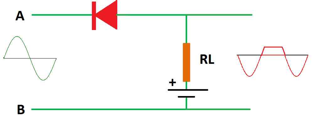
We have discussed two types of clipping circuits which completely clip off one half-cycle of a signal waveform completely.
Now, what if we want to clip off only a portion of a signal? To achieve this we are applying a reference voltage to a series positive clipper circuit as illustrated above.
The above circuit is the same as a series positive clipper except we are applying a bias voltage to the load resistor. The voltage of the battery determines the amplitude of the clipped signal.
Now let’s try to understand the circuit during both the half-cycles.
Now consider that we are applying +Ve at point A and –Ve at point B. The diode is reverse biased and no current will reach the output, but since we have a voltage source in series with a load resistor, the voltage from the battery is passed to the output; hence we get a positive voltage on the graph.
Now consider applying –Ve at point A and +Ve at point B. The diode is forward biased and when the input voltage exceeds the bias voltage (battery), the output goes negative.
Series Positive Clipper with Negative Bias:
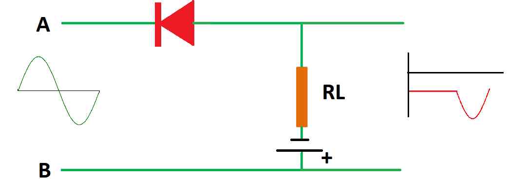
The above circuit is same as the previous one except the bias voltage is in reverse polarity.
Now let’s consider applying +Ve to point A and –Ve at point B.
Now the cathode of the diode is connected to +Ve of the input supply, the diode is reverse biased and acts like an open circuit.
Since a battery is connected at the output, we will see the output voltage equal to the battery (flat portion of the graph).
Now considering we are applying –Ve to point A and +Ve to point B, the diode gets forward biased and conducts the input voltage to output.
As long as the input voltage is below the battery voltage we will see a voltage equal to battery potential, but when input voltage exceeds the bias voltage we will see negative peak voltage as dictated by the input.
Series Negative Clipper with Positive Bias:
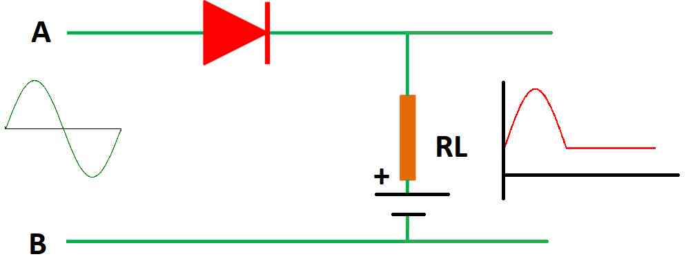
In this clipper circuit the diode has switched its terminals compared to the previous type. Now let’s see what happens in each half cycle of the input.
Now let’s apply -Ve to point A and +Ve to point B. The diode is reverse biased and no voltage will reach the output, but since we have a voltage source, the output will be equal to the source voltage; we can see the flat portion of the graph.
Now let’s apply +Ve to point A and –Ve at point B. Now the diode is forward biased and input voltage reaches the output.
There will be no change in the output voltage if the input is below the source voltage because the bias voltage is dominant, but when input voltage exceeds the source voltage we will see a positive spike as dictated by the input signal.
Series Negative Clipper with Negative Bias:
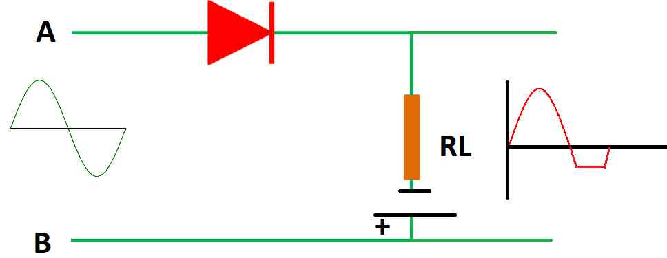
In this circuit we just reversed the bias source polarity; now let’s see what happens for each half cycle.
Let’s apply –Ve to point A and +Ve at point B.
Now the diode is reverse biased because the –Ve polarity of the input is connected to the anode of the diode, hence no voltage at the output.
Since we have a bias voltage, the output will be equal to bias battery potential and that’s why we are observing a negative voltage on the graph.
Now let’s reverse the polarity of the input supply. Now the diode is forward biased and when the input voltage exceeds the bias voltage we will see positive voltage on the positive quadrant of the graph.
This concludes the series clipper circuit.
Shunt clipper:
Shunt clippers perform the opposite function of series clippers; the input gets conducted to the output when the diode is reverse biased, which is opposite to the series clipper.
Shunt Positive Clipper:
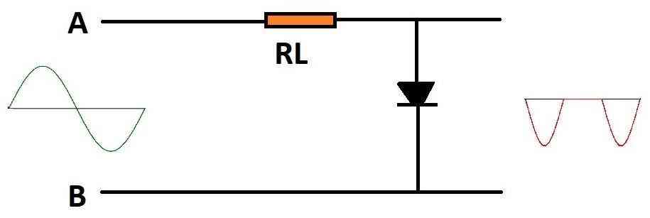
A shunt positive clipper is illustrated above, the load resistor is series with the input signal and the diode is parallel to the output. Let’s try to understand what happens at both half cycles.
Now let’s apply +Ve to point A and –Ve to point B. The diode is forward biased because the anode is connected to +Ve of the input and the diode will route the signal back to the input source. The diode acts as a low resistance return path for the input signal, hence no output.
Now let’s apply –Ve to point A and +Ve at point B. The diode is reverse biased and the diode acts like an open circuit and the input signal will appear at output, hence we see negative cycles at the output.
Shunt Negative Clipper:
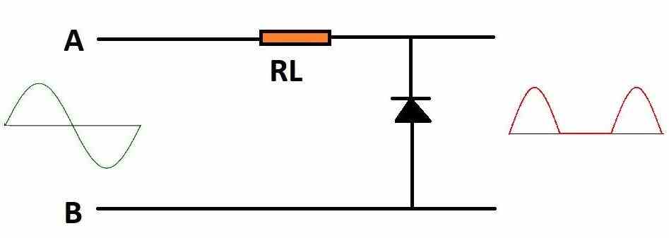
In the shunt negative clipper circuit the diode’s position is reversed, let’s understand how it works on both the half cycles.
Let’s consider +Ve at point A –Ve at point B. The diode is reverse biased as the cathode of the diode is in contact with +Ve of the input.
Now the diode acts like an open circuit and hence the signal appears at the output.
Now let’s apply –Ve at point A and +Ve at point B.
The diode is forward biased and acts like a low resistance return path and the signal gets returned back to the input source for this half cycle, hence we see no negative half cycle at the output.
Shunt Positive Clipper with Positive Bias

The above circuit is a positive shunt clipper with a biasing voltage. Let’s apply the same rules as before and determine the output.
When we apply +Ve at point A and –Ve at point B, the diode is forward biased but the bias voltage tries to make the diode partially reverse biased, hence we will get a positive voltage at the output that is clipped.
Now if we apply –Ve at point A and +Ve at point B, the diode is reverse biased and the diode becomes open circuit and the negative half cycle is unaffected.
Shunt Positive Clipper with Negative Bias:

The above circuit is the same as the previous except the bias voltage polarity has been reversed.
Let’s apply +Ve to point A and –Ve to point B, the diode is forward biased and acts like a closed switch and the bias voltage also makes the diode forward biased.
Now the input and the bias voltage (the two voltage sources) are connected in series, but since the output is taken across the bias voltage, only the bias voltage appears at the output (flat part of the graph).
Now if we reverse the input polarity the diode is reverse biased and the voltage appears at the output, but the bias voltage makes the diode forward biased and this voltage potential will also appear at the output.
If the input voltage at this negative half cycle is less than the bias voltage, the bias voltage will dominate at the output. If the input voltage is greater than the bias voltage, input voltage will dominate the output.
Shunt Negative Clipper with Positive Bias:

In this circuit the diode’s polarity is reversed and a positive bias is applied. Now let’s apply the rules.
When we apply +Ve to point A and –Ve to point B, the diode is reverse biased, but the bias voltage will forward bias the diode and the battery voltage appears at the output.
When the input voltage at positive half cycle is more than the bias voltage, the input voltage dominates the output and when input voltage is less than bias voltage, the battery voltage dominates the output.
Shunt Negative Clipper with Negative Bias:

In this circuit the bias source voltage is reversed and let’s apply the rules to find the output.
When we apply +Ve to point A and –Ve to point B, the diode is reverse biased and the bias voltage also causes the diode to be reverse biased, hence the diode acts like an open circuit and the input signal is not clipped.
When we apply –Ve to point A and +Ve to point B, the diode is forward biased and the bias voltage causes the diode to be partially reverse biased, hence we will get an output voltage that is clipped as illustrated above.
If the input voltage in the negative half cycle exceeds the bias voltage, the diode starts to conduct fully and the signal is routed back to the source and no signal appears at the output.
Dual clipper circuit:

The above illustrated circuit is called a dual clipper, it is also called a combinational clipper. It consists of two diodes and two bias voltage sources in anti-parallel.
Till now whatever the circuit I will explained only clips off any one of the half-cycles, but this circuit clips off the signal in both the half-cycles.
Let’s apply +Ve at point A and –Ve at point B, the diode at the left hand side gets reverse biased and its bias source voltage also reverse biases the diode and hence the diode acts like an open circuit.
The diode at the right hand side gets forward biased and gets reverse biased partially by its bias source voltage; due to this the output voltage (positive half cycle) gets clipped to the level of bias voltage.
Now, let’s reverse the input voltage. The diode at the right hand side gets reverse biased and it acts like an open circuit.
The diode at the left hand side gets forward biased and its bias voltage makes the diode partially reverse biased, hence just like the previous condition the output (negative half cycle) gets clipped to the potential of bias voltage.
Please note that if the input voltage exceeds the both the bias voltages, no output will appear because the diode starts to conduct fully like a low resistance path.
This includes different types of clipper circuits.
Clamper circuit:
What is a clamper circuit?
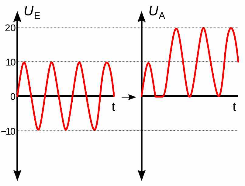
A clamper is a circuit arrangement using a capacitor, diode and resistor. A clamper circuit does not change the appearance of the waveform (like clipper does), but it shifts the incoming wave above zero point or below zero point on the voltage graph. Shifting of the waveform is achieved by applying a DC offset to the incoming AC signal.
We can also define a clamper circuit in other words: The wave shape of a signal is unaltered but its peak to peak value is changed by applying a desired DC offset voltage as illustrated below:
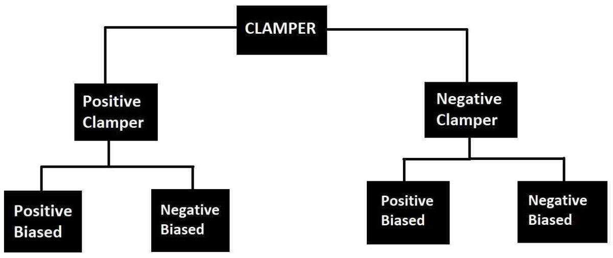
Classification of Clamper:
Positive Clamper Circuit:

The above clamper circuit consists of a non-polarized capacitor, a diode and a load resistor; this circuit shifts the input AC signal towards the positive side of the graph without altering the shape of the wave as illustrated above.
A clamper that shifts the output waveform more towards the positive quadrant of the graph is called a positive clamper. Now let’s try to understand how the above circuit works.
Now let’s apply –Ve to point A and +Ve to point B, the diode is forward biased and charges the capacitor and its negatively charged terminal is at point A and its positively charged terminal is on the other side.
Now when the next half cycle kicks in, +Ve input is at point A and –Ve to point at B, if we observe closely the input and the charged capacitor are in series and the diode is reverse biased / open circuit.
At this instant the output is: OUTPUT = Vin + Vcap.
Now the output will respond as per the input signal and the level of positive shift is determined by the charge in the capacitor.
Negative Clamper circuit:

The above circuit is self-explanatory and is similar to the previous circuit; the only difference is the diode’s polarity is reversed and the signal is clamped below zero point.
Positive Clamper Circuit with Positive Bias:

A bias positive clamper looks as illustrated above; let’s try to understand how it works.
Now let’s apply –Ve to point A and +Ve to point B, the diode is forward biased and the capacitor gets charged.
If you observe closely, this negative input half cycle and bias voltage are in series and the capacitor gets charged with two voltage sources .i.e. the input voltage and the bias voltage, this increases the clamping level.
In the next (positive) half cycle, the capacitor and the input source will connect in series and the output voltage is = Vcap + Vin, hence we will get an output that is illustrated in the above image.
Positive Clamper Circuit with Negative Bias:

The above circuit is similar to the previous; now the bias voltage polarity is reversed.
Let’s apply –Ve to point A and +Ve to point B, the diode gets forwards biased and charges the capacitor, now the input and the bias voltage are in series but these two voltages don’t add-up instead gets subtracted, because of the polarities of input and bias voltages, hence the capacitor won’t get charged fully and we will get a negative peak below zero point proportional to bias voltage.
In the next (positive) half cycle, +Ve at point A and –Ve at point B, the diode doesn't get forward biased and the capacitor and input get added up and we will get output voltage as illustrated in the above image.
Negative Clamper with Positive Bias:

In this circuit the diode’s polarity is reversed compared to the positive clamper and a positive bias source is introduced.
Let’s apply +Ve to point A and -Ve to point B, the diode is forward biased and charges the capacitor but it won’t charge the capacitor fully because the input and bias voltages are connected in series but in subtraction polarity (as explained in the previous section).
Hence we will get a positive waveform as dictated by a bias voltage.
Now if we apply –Ve to point A and +Ve to point B, the diode is reverse biased and in the input and capacitor voltages add up and the output will be as illustrated above.
Negative Clamper with Negative Bias:

The above circuit is similar to the previous; now the bias voltage has been reversed.
Now let’s apply +Ve to point A and –Ve to point B, the diode is forward biased and charges the capacitor, the input and bias voltages add-up and charges the capacitor above input voltage.
Now in the next (positive) half cycle, the capacitor and input voltages add-up and we will get the output as illustrated above.
This concludes different types of clamper circuits.
Post your comments here and get guaranteed replies. Comments must be related to the above article.