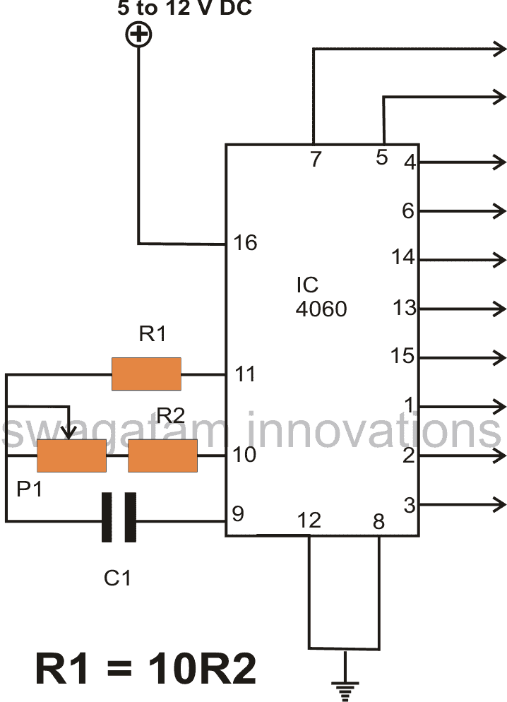
Another versatile device, the IC 4060 has numerous applications and can be used for implementing various useful functions in an electronic circuit. Introduction Basically the IC 4060 is a oscillator/Timer IC and can be used for producing discretely variable accurate time intervals or delays. Alternatively it may also be used as an oscillator for acquiring […]
Explained
Light Emitting Diodes (LED) Explained
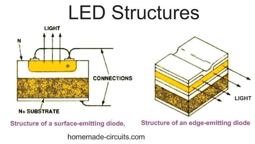
The full form of LED is Light Emitting Diode. LEDs are special type of semiconductor diodes which emit light in response to a potential difference applied across their terminals, hence the name light emitting diode. Just like a normal diode LEDs also have two terminals with polarity, namely anode and cathode. To illuminate an LED […]
SMPS Spot Welding Circuit using IC SG3525 Explained
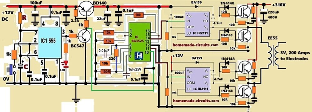
Spot welding needs very low voltage but very high current, that too for very short time, so now this whole thing is built around that idea. In this design we push big current in small time period for safely creating the required welding joint, done. Audio/Video Representation How the Circuit Works Now the circuit, it […]
4 Automatic Staircase Lamp Controller Circuits Explained
In this post I have explained 4 innovative automatic staircase lamp controller circuits which will automatically switch ON and OFF the staircase lamps in response to an external trigger. We will discuss 4 concepts here, which are as follows: 1) Automatic Staircase Lamp Circuit using PIR The first automatic staircase light circuit describes a simple […]
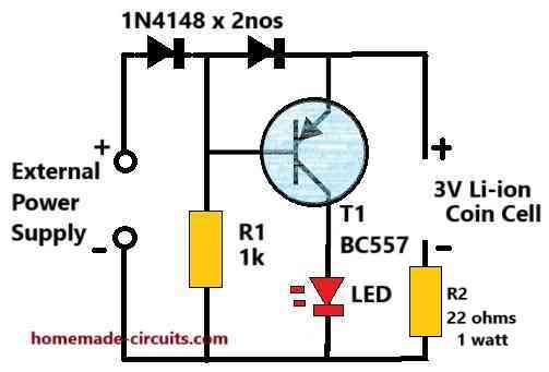
2 Best Current Limiter Circuits Explained
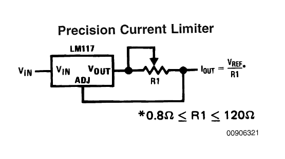
In this post I have explained 2 simple universal current controller circuits which can be used for safely operating any desired high watt LED. The universal high watt LED current limiter circuit explained here can be integrated with any crude DC supply source for getting an outstanding over current protection for the connected high watt […]
5 Useful Power Failure Indicator Circuits Explained
In this post I have explained 5 useful power supply failure indicator circuits which can be used to get an instant indication regarding an input power failure situation. This post includes the following 5 types power failure indicator circuits: Main Function The main function of the proposed power failure indicator circuits is to alert or […]