In this post, I will show how to construct a laser security circuit which can send SMS alert to owner of the property or anyone else and activate loud alarm to deter the crook, which can be interfaced via relay.
We always fear about crooks especially when we leave our property alone, this where security systems come in handy. Loud alarm may be enough to grab everyone’s attention nearby area and deter the thief.
SMS alert warns the user to take necessary action just after the crook broke in to your property.
The security systems should be implemented at week points of your house/office, such as doors and windows, sometimes multiple numbers of security systems are required for maximum protection against thief at different points of your home or office.
How it Works
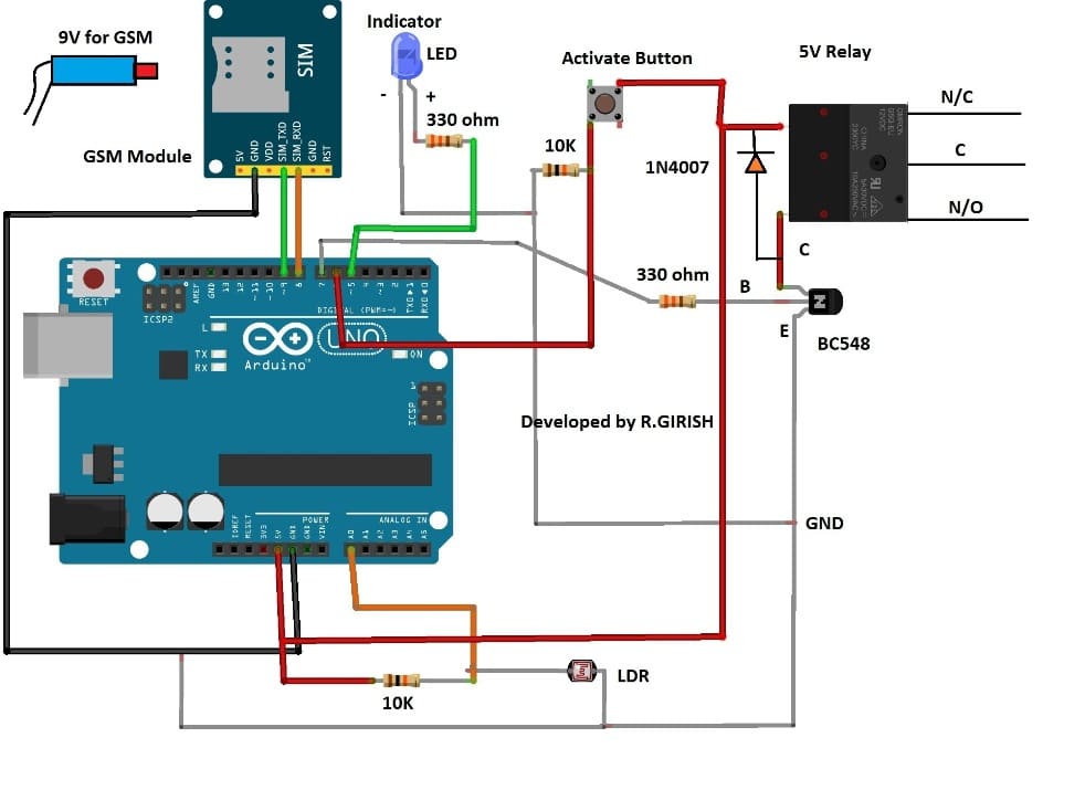
NOTE: Please replace the transistor base resistor 330 ohm with a 10 K resistor, because 330 ohm value is too low and is incorrect.
The circuit consists of Arduino, which sense intrusion and take decisions. GSM modem receives command for sending SMS to user and few other passive components to detect intrusion.
The Arduino scans the laser beam for interruption in light 500 times a second. The LDR senses the presence laser light and gives signal to Arduino.
The 10K and LDR forms voltage divider, the analogue signal is taken from a point between these two components.
When the incident light intensity reduces to certain degree or light completely cut-off the arduino recognize as intrusion.
The 10K resistor which is connected to “activate button” acts as pull down resistor to prevent the arduino pin from activating randomly.
The transistor activates the relay in case of an intrusion and the diode protects the rest of the circuit from high voltage spike while switching the relay on and off.
You can connect a siren or lights or whatever you wish to connect to relay.
To activate the security system, we have to press the activate button, the LED indicator confirms that the button is pressed.
The system gets activated only after 2 minutes; this will give time to lock you property and leave the place.
When you return home, to deactivate the system press the reset button. Solder a push-to-on button from reset button terminal of Arduino, so that the reset button to deactivate the system is easily accessible from outside the setup.
Once the circuit detected intrusion, the relay will be activated for 2 minutes and it turns off and it will be ready to detect next intrusion.
The GSM modem need external power supply as arduino can’t provide enough current to the module. Please insert a valid SIM card with a working SMS plan.
That’s all about this SMS based laser security circuit; now let’s see how to implement the setup in correct way.
How to implement the setup:
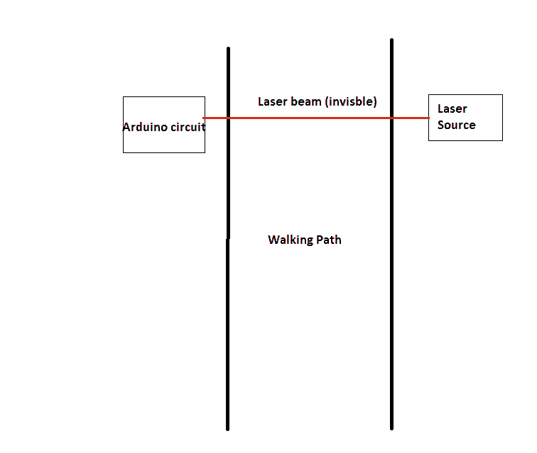
Place the laser source and arduino circuit in such a way that the laser light falls exactly on LDR. You can also try mirrors reflecting the laser beam to cover a large area.
If you own pets and to prevent accidental or false alarm, elevate the whole setup to hip level of an adult. You pets will go under the laser beams preventing false triggering.
The LDR is susceptible to errors/false alarm when ambient light falls on it. To avoid these kinds of errors, we need to enclose the LDR with opaque hollow cylinder with one end open and other end closed made up of plastic or any other material.
LDR Setup
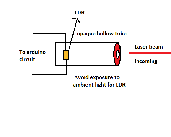
Make sure the front portion of the tube is covered as well and only tiny hole with few millimeters in diameter for entering laser beam.
When the laser beam falls on the LDR the value read by the arduino is low but when light interruption is detected the value will go to peak at the same instant, which you can witness the same from serial monitor.
Once the light intensity goes below the pre-determined threshold, arduino trigger the relay and send SMS alert to the user.
Program Code:
//--------------Program developed by R.Girish---------------//

#include <SoftwareSerial.h>

SoftwareSerial gsm(9,8);

int LDR = A0;

int OP = 7;

int start = 6;

int LED = 5;

int th = 300;

int x;

unsigned long A = 1000L;

unsigned long B = A * 60;

unsigned long C = B * 2;

void setup()

{

Serial.begin(9600);

gsm.begin(9600);

pinMode(LDR,INPUT);

pinMode(OP,OUTPUT);

pinMode(start,INPUT);

pinMode(LED,OUTPUT);

}

void loop()

{

if(digitalRead(start)==1)

{

digitalWrite(LED,HIGH);

delay(C);

A:

x = analogRead(A0);

Serial.println(x);

if(x<=th)

{

delay(2);

goto A;

}

if(x>=th)

{

digitalWrite(OP,HIGH);

Serial.println("Sending SMS......\n");

gsm.println("AT+CMGF=1");

delay(1000);

gsm.println("AT+CMGS=\"+91XXXXXXXXXX\"\r"); // Replace x with mobile number

delay(1000);

gsm.println("Security Warning: Intruder detected."); // The SMS text you want to send

delay(100);

gsm.println((char)26); // ASCII code of CTRL+Z

delay(1000);

Serial.println("Message is sent\n");

delay(C);

digitalWrite(OP,LOW);

goto A;

}

}

}

//--------------Program developed by R.Girish---------------//
Please replace the “XXXXXXXXXX” with your phone number to receive SMS.


Comments
Do you have a wiring diagram
Hello Mr Swagatam
I have gone through this post , noted that modification on Aduino Code falls under premium projects ,
I require a quote on some code modification for the above project post for my specific solution , I may have to send to it through to your email
regards
Hi Vhafuwi, sorry Arduino coding not being my area of expertise would be difficult to address, and approaching the actual author may be also difficult at the moment for me. Kindly bear with me!
Hi
Pls am done with the project and tested it, everything is working but am not receiving SMS from the GSM. So pls help me out whether there is a problem with the coding.
Hi Gycon,
Open the Serial monitor and try triggering the circuit. You must see “Message is sent” on serial monitor, if yes the circuit is triggered and Arduino is communicating with GSM. If no SMS to your mobile phone, check you connection to GSM module, still no results. Check your GSM module is properly working or not.
Regards
Mr. GR will reply you soon.
Hello, i tried this project, i have GSM, SIM 900A.. the problem is
1) i can’t connect the relay on breadboard?
2) also if i use USB to power up Arduino where should I place the connection for LDR?
3) IS there any video available for thos project as a result?
4) what changes do i have to make in the program?
Hello, all the connections are already given in the diagram, the LDR connection is also shown…
there’s no video for this…
hi
pls which part of the circuit is the relay output terminals connects to
The relay coil connects with the transistor. For more on relay connections you can refer to the following post:
https://www.homemade-circuits.com/community/electronic-circuit-forum/how-a-relay-works-in-circuits-how-to-connect-it/
Hi
Pls am done with the wiring of the diagram and uploaded the program to it but am not having any feedback. Pls kindly help me out.
Am talking of the SMS and the LED which suppose to light up as the output results.
Hi Gycon,
I didn’t get you….. can you elaborate what feedback do you mean.
Regards
Hi
Pls on the GSM which pins is meant for the external power
Hi Gycon,
The external power to your GSM module is the DC jack generally. The external “pin” on your GSM module may be differ from mine, so search your model on google or just take closer look on the board it will be named as “Vcc” or “12V” something similar.
Regards
Hlo sir..
I want such kind an project in which an megnatic switch turns on the one specific pin of arduino to make a call from gsm module to a mobile number…
Plz explain me the complete circuit and the parts list….this project is very important for me…
Not an notifying msg is required…
Just an call by turning on the read switch….
Rakesh41035@gmail.com
Thank u.
Hi Rakesh,
From you comments what we can understand is:
You want to get a call from the GSM module to a mobile number, if the magnetic switch (reed switch) is triggered.
Shall we confirm your requirement? and proceed?
Regards
Yes sir i want to manage a call by triggering (on/off)the read switch ….
And the call must be repeated until the call is being not answered….
Hi Rakesh,
Let’s make the technical aspects of your project clear once again,
When the reed switch is triggered you will receive a call to your phone and the call ring to your phone lasts 40 to 50 seconds, it is your wish to cut the call or not. But anyways the call gets disconnected (by the mobile network) after 50 seconds automatically and you will get missed call notification.
The pricing for the project:
For Each word explanation is 1 rupee. (Around 500 words of explanation is expected, but can vary)
For Each line of program code is 10 rupee. (Around 100 to 150 lines of code is expected, but can vary)
Regards
Hello Rakesh,
presently all Arduino related projects are premium projects, so you may have to pay for the customization, or have to buy the entire kit from us.
Okkk sir…
How much i hav to pay for this article ????
I’ll forward this question to Mr. GR, he will reply you regarding the price soon…
Hello sir Some problem gsm.println(“AT+CMGS=”+91XXXXXXXXXX”r”); // Replace x with mobile number
delay(1000); please solved.And e-mail me code for project.
Hello siamfj, I’ll forward this question to Mr. GR, he will solve the issue for you soon…
Hi siamfj,
The corrected code will be placed soon.
Regards
Thank you GR,
I have made the necessary corrections, I hope the system will work correctly now.
i am AUTOMATION & ROBOTICS ENGINEER
GSM Module how it cost ?
kind regards
Malek
You can search online for the rates, you can find it easily
Hi,SWAG. i am really grateful to you for making your circuits open to all God will bless you abundantly.
Pls kindly assist me in this project, i want to build a security system whereby the system will send sms or message to numbers and location using gprs.
Thank hoping to hearing from you soonest from Kelvin
Thanks Offor, I am glad you liked the circuits. The Arduino circuits are not designed by me, they are designed by Mr.GR, so I’ll inquire with him and get back to you soon with the reply. By the way why GPRS is required here? Please enlighten me about this….
gsm.println(“AT+CMGS=\”+91XXXXXXXXXX\”+91XXXXXXXXXX\r”); // Replace x with mobile number
above example is possible ?can we add two or more number!!!?
Hi! I would like to make this project together with my classmates for our subject Spectra. Do you have a list for the components used in this? Thank you very much!
Hi, I am glad you have selected this project!
All the parts shown in the diagram are standard parts, you just have to copy them as given in the diagram and show it to the shopkeeper…the shopkeeper will understand and provide them to you appropriately.
Please click the diagram to get an enlarged view of it….
Thank you
What is "ASCII code of CTRL+Z" ? Can i change the activation time??
Hi Jade,
It is termination character for sending SMS, after sending SMS we have to terminate the process.
On which part you want to change activation time? Can you elaborate please.
Regards