This test set is primarily designed to test step-down, step-up transformers, for open and shorted winding. It can determine if the device under test has a low resistance to ac current. It can also measure the dc current resistance
in ohms.
By Henry Bowman
Introduction
The test set uses a 16 VAC, 60hz signal to determine the AC load resistance in ohms. DC ohmmeters are useless for testing transformer shorts, due to low dc resistance of normal windings. To use this tester, let's forget about the voltage and current phase relationships in ac circuits, and just look at how alternating current alone is affected by coil resistance.
Circuit description:
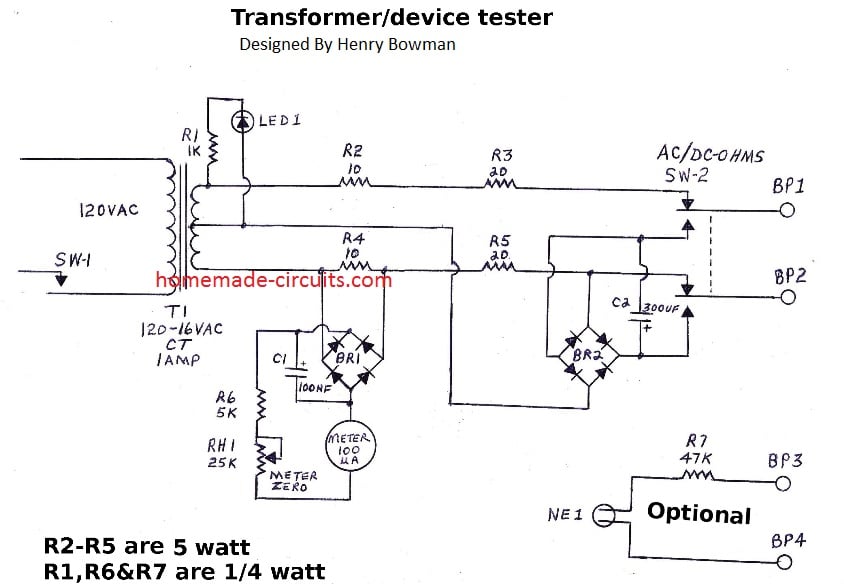
Switch Sw-1 provides 120 VAC power to transformer T1, which steps down the AC line voltage to 16 VAC. LED 1 and R1 provide a power-on indication.
The tester must be calibrated before using (see calibration below). When SW-2 is in AC ohms position, a 60HZ, 16 VAC signal is applied to BP1 and BP2.
This AC signal is in series with current limiting resistors R2-R5. When the primary side of a step-down transformer is connected to BP1 and BP2, the AC current flow will cause a voltage drop across resistors R2-R5.
Bridge rectifier BR1 rectifies the voltage drop across R4 (10 ohms) and converts it to dc.
C1 provides filtering of the DC signal. R6 and RH1 provide the necessary resistance to the 100 micro-amp meter. When properly calibrated, the meter will provide the AC current reactance, in ohms, of the connected load.
Switching SW-2 to DC ohms connects a second bridge rectifier to BP-1 and BR-2.
It disconnects the upper half of the transformer and uses the lower half which is 8 volts ac. BR2 rectifies the 8 vac to dc. R4 & R5 are still in series with the 8 VAC and R4 provides the DC voltage drop to the meter. Very little meter zeroing is required between the AC/DC testing. The DC ohms function should be limited to testing coil winding continuity of transformers.
Circuit Diagram
Construction Hints:
I used point to point wiring with a small perforated circuit board. While I specified 5 watt resistors for this project they are satisfactory for short intervals of testing. If long periods of testing are required, the 5 watt resistors should
be replaced with 10 watt.
The perf board should be placed inside a small metal or plastic enclosure. Some vent holes should be provided for heat dissipation from the 5 watt resistors. A cut out should be made for the meter and holes drilled for SW-2, RH-1, BP1, BP2. If the optional circuit consisting of BP3, BP4, R& and NE1 are used then holes need to be provided for NE-1, BP3 and BP4.
Be sure that one AClegs of BR-2 are correctly connected as shown on the schematic. The power indicating LED and series resistor can be connected to either side of the secondary winding and the center tap. Since the led is a diode, no diode in series is required.
Test Set Calibration:
The meter you select must be able to provide a good spread between zero and 50 ohms and be able to read at least 100 ohms of resistance.
If it's difficult to determine if the AC resistance is 20 or 30 ohms, then you won't be able to determine the amount of current being consumed by the device under test. Using a meter other than 100 micro-amp may require changing the value of the load resistor R4 and/or changing R6 & RH1 values.
When construction is completed, adjust RH1 for maximum resistance and power up the test set. Connect test clips to BP1 & BP2 to provide a short circuit. Adjust RH1 for full scale meter deflection (zero ohms). Remove the short and select the following resistors for calibration: 5, 15, 25, 50, 75, and 100 ohms.
Remove the meter face and use white-out to remove the existing numbers on the meter face. If the meter face is not removeable, you will have to apply an adhesive label on the front of the meter.
Connect the 100 ohm resistor first, to BP1 & BP2. Place a mark on the scale where the pointer indicates (you may want to stencil the actual values later). Continue with the next lowest resistance until all are marked.
Switch SW-2 to the dc position, zero meter and recheck values. There should be very little calibration between ac and dc settings.
Re-zero your meter on the ac scale before testing.
Test Set Use:
Connect the test set (BP1 & BP2) to the primary side of a junk box 120vAC step-down line transformer. Remember that we are connecing 16 VAC to the transformer.
A step-up transformer while testing could provide a hazardous voltage on the secondary. Select AC ohms on the tester and turn it on. If the transformer has no shorted turns, the meter will not have a reading.
Although there is some high ac resistance in the transformer, we're only interested in low resistance values. Place a temporary short on the secondary.
The meter should now indicate a low resistance reading on the primary. The actual resistance is determined by the number of turns in the primary & secondary windings. Remove the short on the secondary and switch to DC ohms on the test set. Re-zero the meter if necessary.
The DC ohms should be very low, indicating that the ac resistance is much higher. Shorting the secondary coil, while in dc test will have no effect on the resistance reading. If you installed the BP3 & BP4 option you can try the next step.
If you're very careful while testing, you can reverse the transformer winding connections and connect the secondary windings to BP1 & BP2 and the primary windings to optional BP3 and BP4. BP3 & BP4 can be connected to the secondary of a step-up transformer, or the primary of a step-down transformer. When the 16 VAC from BP1 & BP2 is applied to the connection, the primary winding connected to BP3 & BP4 should light the neon bulb (if a minium of 70 vac is present).
It would be a good idea to take notes of the ac resistances on various known good transformers, for future reference.
Never attempt this test on a microwave transformer, car coil, or other high voltage type transformer !
Testing Faults in other Devices
In addition to transformer testing you can find some applications for other faults in devices. Suppose you have a device that is blowing AC fuses.
Disconnect the defective device from the 120VAC line. Connect this test set’s BP1 and BP2 leads to the ac line cord plugs of the defective device.
Replace the blown fuse in the defective device. Read the AC ohms shown on the meter. Use Ohm’s law for determining current drain. A TV with a 5 amp fuse, would normally consume 3 to 4 amps of current.
Using current = voltage (120) divided by resistance (meter reading), the test set should indicate 30-40 ohms with normal current load. A reading of 20 ohms will definitely blow a 5 amp fuse, so you’ve got to find the problem before powering the device with 120 volts.
You can leave the test set connected and disconnect suspected components, until the meter returns to the normal resistance range. Note: Most tv's have a low voltage relay, which operates when the power button is pressed. The relay operates and connects the B+ to the load.
To use this test set with this type TV, you'll have to figure out how to strap the B+ around the relay. CB radios, scanners and other devices that operate on 120vac can tested with this tester. Never attempt to test a device that is powered by DC. This test set will not trouble shoot electric motors or other heavy inductive loads.
Happy troubleshooting !
Note:
If you think that an in-service transformer is shorted, or defective, you will have to disconnect the secondary leads to properly test. This would include multiple secondary leads, if equipped.
Parts list:
Qty Description
1 Transformer 120VAC-16VAC
1 AC line cord
2 Resistors, 20 ohm 5 watt
1 Bridge rectifier BR-1, 200MA
1 Bridge rectifier BR-2, 500MA
1 Electrolitic capacitor 300UF,25 WVDC
1 Electrolitic capacitor 100 NF, 25 WVDC
1 Panel Meter 100 micro-amp
1 variable resistor 25K ohms
1 Light emitting diode
1 Resistor 1000 ohm 1/4 watt
1 SPST switch
1 DPDT switch
4 Binding post for test connections
1 Neon bulb
1 47K resistor 1/4 watt (not required, if neon has internal resistor)
1 Apparatus box

Comments
Hello sir, please how can I reduce Ac voltage from power grid from 220v to 190v without using a trafo, want it to power a 200w loads
Hello Adeyemi, you can try a light dimmer, triac chopper circuit
Thanks, Thanks and Thanks Chief Swagatam, what a great idea! Hope it won’t affect loads like Tv, fan, etc
You are welcome Adeyemi!
good night Sir Im looking at the transformer tester, is the secondary is two lines of 8v ac the middle grown or 16ac on each one middle grown , nice project
Thank you very much, yes it is a 8-0-8 or 9-0-9V trafo.
I need some schema for my FLY SWATTER – it has these writings on it:
H3U1
29SH
HS-67
DS3939B
AS5732A-1
The transistor and a resistor blew up and I do not know the values, so I’m looking to replace the bad parts, but don’t know what to use. I think the transistor is probably NPN but that is just guessing.
I could suggest better if I had the picture of the board.
Anyway if the transistor is an NPN then you could try an 8050 transistor. If the burnt resistor is at the base of the BJT, you could easily try any value between 1K and 10K. The parts probably blew due to switch ON surge from the capacitive power supply…to prevent this in future connect a 22 ohm 1watt resistor in series with the input mains capacitor.
Thanks for the help! I’ll test the 8050 NPN and the resistor as you suggested.
Sure, all the best to you!
0.1v to 5v postive supply…
If Sudden moment 0.1v or 5v + supply come means the o/p relay must be latched by using opamp or any circuits…
I tried in transistor but it triggers more then 0.34v…so pls guide me sir
Dear sir,
I need one circuit by using op amp sir…
One circuit producing o/p 0.10 to 4v postive supply coming sir…
I used NPN transistor for latching relay..
But it triggers more then 0.50v..
Need to trigger in 0.10v ..
So i think that op amp will do..but i do no the circuit diagram..pls guide me sir
Hi Kesav,
you can try the following concept for making a sensitive transistorized latch
https://www.homemade-circuits.com/simple-and-useful-transistor-latch/
this circuit will trigger with 0.2V inputs, if it doesn’t you can try upgrading T1 with a Darlington pair.
In that case make sure to connect a small value cap such as a 0.22uF across base/emitter of T1
Thank u sir…