In this post I will show how to construct a simple digital ohmmeter circuit using Arduino and 16x2 LCD display. We will also be exploring the other possible circuit ideas using the same concept.
Circuit Objective
The motto of this article is not just making an ohm meter to measure the resistance; your multimeter can better do the same.
The main objective of this project is to use the resistance value read by arduino to do some useful projects, for instance, fire alarm, where the change in resistance value of thermistor can be easily detected or automatic irrigation system where, if the resistance of soil goes high the microcontroller can trigger the water pump. The possibility of projects is up to your imagination.
Let’s see how to make an ohm meter first and then we move to other circuit ideas.
How it Works
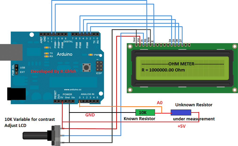
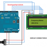
The circuit consists of Arduino; you may use your favorite Arduino board, a 16x2 LCD display to showcase the unknown resistor value, a potentiometer to adjust contrast level of LCD display. Two resistors are used, one of which is known resistor value and other is unknown resistor value.
The resistance is an analogue function, but the value displayed on LCD is digital function. So, we need to do analogue to digital conversion, fortunately Arduino has built-in 10-bit analogue to digital converter.
The 10-bit ADC can differentiate 1024 discrete voltage levels, 5 volt is applied to 2 resistors and the voltage sample is taken in between the resistors.
Using some mathematical calculations, voltage drop at the node and known resistance value can be interpreted to find the unknown resistance value.
The mathematical equations are written in the program, so no manual calculation need to be done, we can read direct value from LCD display.
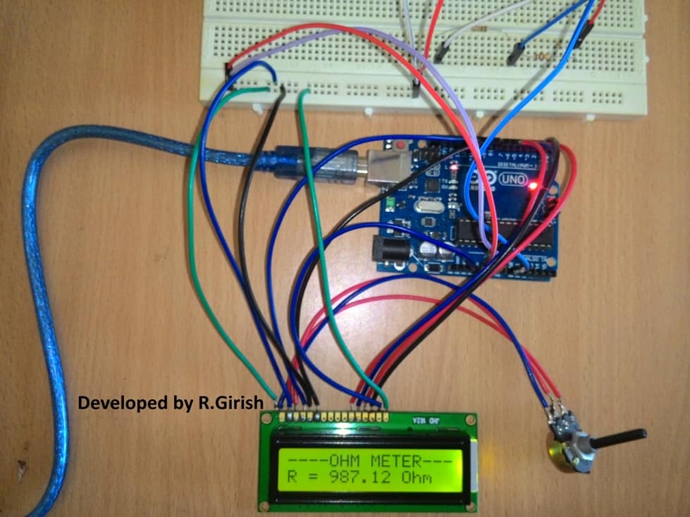
Author’s prototype:
Program for Ohm meter:
//-------------Program developed by R.Girish--------//

#include <LiquidCrystal.h>

LiquidCrystal lcd(12,11,5,4,3,2);

int analogPin=0;

int x=0;

float Vout=0;

float R=10000; //Known Resistor value in Ohm

float resistor=0;

float buffer=0;

void setup()

{

lcd.begin(16,2);

lcd.setCursor(0,0);

lcd.print("----OHM METER---");

}

void loop()

{

x=analogRead(analogPin);

buffer=x*5;

Vout=(buffer)/1024.0;

buffer=(5/Vout)-1;

resistor=R*buffer;

lcd.setCursor(0,1);

lcd.print("R = ");

lcd.print(resistor);

lcd.print(" Ohm");

delay(3000);

}

//-------------Program developed by R.Girish--------//
NOTE: float R=10000; //Known Resistor value in Ohm
You can change the known resistor value in the circuit, but if you do so please change value in the program also.
Like a conventional multimeter, this Arduino digital ohmmeter circuit too has some ranges to measure the resistance. If you try to measure a low value resistor in mega ohm range in your multimeter, certainly you get error values.
Likewise, it is true for this ohmmeter too.
If you wish to measure resistance from 1K to 50K ohm, 10K ohm known resistor will be enough, but if you measure Mega ohm range or few ohm range you will get some garbage readings. So it is necessary to change the value of the known resistor to an appropriate range.
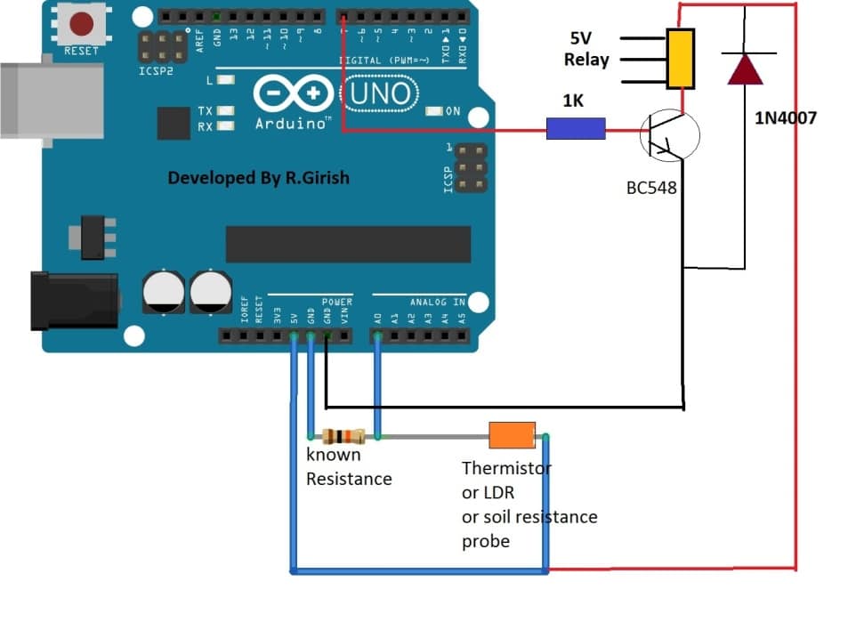
In the next section of this article, we are going to study the LCD display circuit for the ohmmeter; and we will see how to read the sensor value (unknown resistance) in serial monitor.
We will also state the threshold value in the program, once it crosses the pre-determined threshold, Arduino will trigger relay.
Circuit Diagram:
Program Code:
//-------------Program developed by R.Girish--------//

float th=7800; // Set resistance threshold in Ohms

int analogPin=0;

int x=0;

float Vout=0;

float R=10000; //Known value Resistor in Ohm

float resistor=0;

float buffer=0;

int op=7;

void setup()

{

Serial.begin(9600);

pinMode(op,OUTPUT);

digitalWrite(op,LOW);

}

void loop()

{

x=analogRead(analogPin);

buffer=x*5;

Vout=(buffer)/1024.0;

buffer=(5/Vout)-1;

resistor=R*buffer;

Serial.print("R = ");

Serial.print(resistor);

Serial.println(" Ohm");

if(th>resistor) // if resistance cross below threshold value, output is on, if you want opposite result use '<' //

{

digitalWrite(op,HIGH);

Serial.println("Output is ON");

delay(3000);

}

else

{

digitalWrite(op,LOW);

Serial.println("Output is OFF");

delay(3000);

}

}

//-------------Program developed by R.Girish--------//
NOTE:
• float th=7800; // Set resistance threshold in Ohms
Replace 7800 ohm with your value.
• float R=10000; //Known value Resistor in Ohm
Replace 10000 ohm with your known resistor value.
• if(th>resistor)
This line in the program states that, if the sensor resistance goes below threshold value output turns ON and vice versa.
If you want to turn on the relay when sensor reading goes above threshold and vice versa, just replace “if(th<resistor)” with “if(th>resistor)”
By measuring the resistance of the sensor directly (LDR or thermistor or anything else) and setting a threshold, we can acquire great accuracy of control over relay, LEDs, motor and other peripherals.
It is better than comparators, where we set a reference voltage and set threshold by turning a variable resistor blindly to accomplish similar kind of projects.


Comments
Yes . I also tought that by myself . This LED is only indicates that remote is working. ok I will try my self .
OK great thanks!
Back Side of Remote Circuit
https://drive.google.com/file/d/0B8k3jWgWe95XRDQ5V2ZtRVJLQ1k/view?usp=sharing
this side shows only the keppads, the antenna is not visible…the components side is also not showing an antenna connection distinctly.
by the way what's that LED for, is it only for indication?
You will have to trace the antenna by yourself,,,,it will be most probably terminating from a transistor lead….
manually connect a wire randomly to different tracks and see which one alters the range, ….the track which helps to produce the maximum range could be attached with a external wire antenna.
Sir please click the links … I have uploaded 3 photo
One photo is Remote Circuit and Other is Remote Out view And Another is Receiver .. please help me
Transmitter
https://drive.google.com/file/d/0B8k3jWgWe95XbFIycGY3OC04eEU/view?usp=sharing
receiver
https://drive.google.com/file/d/0B8k3jWgWe95XMWdRSEhMLXVlak0/view?usp=sharing
remote
https://drive.google.com/file/d/0B8k3jWgWe95XVi1ramFaV25KX1U/view?usp=sharing
Please show the other side of the transmitter PCB…..
I dont know where is the antina and where need to Connect the Wire
what kind of transmitters are you using? please show example image (link)
Sir i have bought a 12 volt RF LED driver remote and receiver circuit from ebay. I have modified the Receiver Circuit and Removed the LED and Connect a Relay. its working Fine. but range is very poor. But i have noticed that whenever i touched the Remote with an iron stick or any long cable then its works from long distance. I dont know how can i Make it long distance
Sharoj, just increase the length of the transmitter antenna using a 1 feet long wire, that will solve the issue…