In this article I have explained how to make a sequential LED array light circuit with an sequentially illuminating LED forming a bar graph kind of LED formation.
Introduction
In this article I have explained a simple method of making an incremental LED light using the IC 4017, which is rather equipped with specifications not suiting the present functions.
Let’s learn how we can mod the IC for the operations.
The LEDs start from one of the 10 pin outs of the IC and go on switching one after the other until all the LEDs are lit forming an incrementing lighting.
The circuit uses the ordinary IC 4017 for implementing this interesting LED light sequence.
Circuit Operation
The main component of this sequential LED driver circuit is the popular Johnson’s Decade Counter IC 4017.
As we all know, the normal functioning of the IC involves sequential shifting of its outputs 1 to 11, in response to a clock signal applied at its pin #14.
The outputs become high in sequence such that the previous output becomes low immediately as the “high” position “leaps” through the assigned pi-outs.
If LEDs are connected to the outputs, the above sequence would produce an effect of an illuminated “dot” jumping from start to finish and repeating the sequence.
Circuit Diagram
Though the effect looks interesting, fails to bewitch the folks simply because the illuminations produced are very low.
This is because, only one LED or lamp glows at any instant while sequencing, not enough to make the system very eye-catching.
However the sequencing factor of the IC cannot be ignored as it’s one complex function that cannot be achieved a single IC and the chip must be credited for this attribute.
So, what can we do to improve the above feature such that the engaged lights become more attractive and the sequencing feature is also exploited at the same time?
One idea would be to stop the former LEDs in the sequence from shutting down while the array is sequencing.
It means now as the illuminating sequence begins, the LEDs light up one after the other to form an illuminated “bar,” until the whole array is lit up. Once the whole sequence ends, the entire LED string is shut off and the cycle repeats all over again.
However since it won’t be possible to do any modification inside the chip, probably doing this through external amendment is the option left.
To keep the LEDs hold their illuminations even with the sequencing logic going low, we would require some kind latching arrangement with the LEDs for implementing the trick.
As we all know an SCR is one device which latches up its output pin outs when its gate is triggered.
The function is available only with DC supplies though, and here the circuit being operated with a DC, becomes perfectly suitable for the above application.
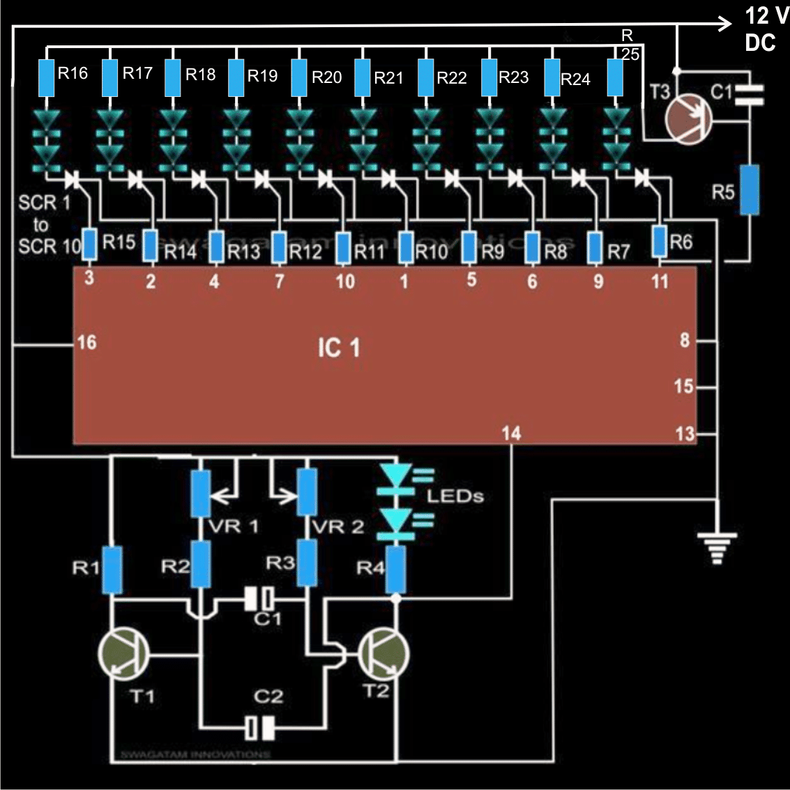
Referring to the figure we see that all the output pin outs of the IC are configured to the gates of the corresponding SCRs, and the LED are connected across the positive and the anodes of the scr.
When the IC outputs start generating the shifting pulses, the SCRs close one after the other, illuminating the LEDs in sequence and latch the illuminations in the incrementing order until the last LED is lit. After this the whole array switches OFF.
The switch-off feature of the LED chain is implemented by T3 and is introduced exactly for this function.
T3 being a PNP transistor, remains switched ON as long as the output at pin #11 is low. Pin #11 being the last pin out in the whole sequence remains at logic low until the sequence concludes over it, making it also go high.
As soon as pin #11 becomes high, the base of T3 is inhibited from conduction, switching off the power to the LEDs and the SCR.
The SCR latch breaks, shutting off the whole array and the sequence gets initiated again from LED 1 at pin #3.
The shifting or the sequencing of the outputs is directly depended on the frequency of the input clocks, applied at pin #14 of the IC.
Any astable multivibrator may be used for sourcing the clocks. Here we have used the common transistor type of AMV, which is perhaps the most simple to build and configure.
C1 and C2 may be varied for getting different clock pulses that would in turn decide the forming rate of the LED bar.
Alternatively you may add VR1 and VR2 in series with R2 and R3 for directly varying the display rates as desired.
The capacitor at the base of T3 is placed so that the transistor switches after a while, and allows the last LED at pin #11 to light up completely before the whole “array” gets shut off.
Resistors R5 to R15 are included to restrict the current to the SCR and also to stop the IC from getting unnecessarily heated up.
The circuit may be operated right from a supply range of 5 volts to 15 volts DC. If the supply is selected 12 volts, 4 LEDs can be accommodated with a series limiting resistor (not shown in the diagram, but is required).
Parts List
- R2, R3 = 10K = 2
- VR1, VR2 = 47K = 2
- Remaining all resistors are = 1K
- C1, C2, C3 = 10uF, 25V = 3
- T1, T2 = BC547 = 1
- T3 = 2N2907 = 1
- All SCRs are = BT169 = 10
- IC1 = 4017 = 1
- All LEDs 20mA, 5mm, Color As per choice = 20


Comments
can i add 10 or more 5mm led to one pin total 100 or more? what changes i need to do.its for decoration
For a 12V supply you can add parallel strings of LEDs on each SCR, each string can have 3 LEDs in series with a limiting resistor. The resistor can be a 100 ohm resistor. Number of parallel strings can be upto 5, meaning a total of 5 x 3 = 15 LEDs on each SCR
Thank you for the reply. Looked at the link you gave me and will give it a try. Again I must be missing something.
Sure, no problem.
Replaced 2907 and added led in sereis with r5. Leds now reset, but led at pin 11 remains on and does reset with others but turns right back on. Replaced scr still no difference also after running for a while other random leds turn on out of sequence but also reset and turn right back on just like led at pin 11. Tried .01 cap across voltage source-no difference. Thanks
It may be difficult to troubleshoot your circuit without practically checking it. There’s another similar circuit presented in the following article, you can see the videos, how it works without any issues.
https://www.homemade-circuits.com/sequential-bar-graph-turn-light/
Built circuit as shown at beginning of article. Used a 555 as my time base. Leds sequence properly, but base of 2n2907 remains at 12v. So led on pin 11 is on at the start of sequence and all leds do not reset. Removing R5 and base of 2907 is always 12v. Pin 11 is cycling as it should. With r5 removed the led at pin 11 cycles normally and all leds remain on No matter what I try the base remains at 12v. Obviously I am missing something. Thank you in advance
R5 is there to protect T3 transistor, it has no relation to the sequencing of the LEDs. Pin 11 LED is connected through an SCR, so it should not glow until pin11 is high, because the SCR would not be conducting until then.
I am not sure what you mean by T3 base is always 12V, are you measuring the base voltage with respect to ground….no, you must measure the base voltage across base and emitter, not base and ground.
Please do not remove R5, it is required to protect T3, and make sure to check T3 again, may be it is already blown by now.
If you are seeing pin11 LED always ON, that is very strange, but you can try controlling it by adding a 1N4148 diode or an LED in series with R6
Thank you for the reply. Yes I was measuring from base to ground. When I measure base to emitter I get .86v. I understand the function of r5 and it cycles like it should at pin 11. Looking at wave form at pin 11 it goes from 0 to 12v in a regular pattern, at base it shows 12v-but that is referenced to ground on scope. Still does not reset and pin 11 led is always on. Will try your suggestions when I have more time. Thanks again
Yes the base emitter may be 0.86V only as long as pin11 is 0 V. As soon as pin11 turns 12V, the base emitter must turn 0 V. If it is not turning 0 V then there may be some problem with the IC or the transistor. In that case you can also try connecting 1n4148 diode between emitter and the positive line to correct the issue.
Mr. Swagatam, hello again!
I asked a question from a different post regarding unused outputs on cascaded 4017s and now I have found this circuit! I think this circuit would be even more useful than the one I was working on. However, the link provided above does not work regarding cascading (2) 4017s. I tried finding it myself using the search function but didn’t have any luck. So, (I hope I’m not being a pest) I would need to know how to cascade two 4017s with the idea from above and I only need 13 outputs. I am repairing a really nice old tin “Santa stop here” sign that had been illuminated with incandescent lamps. Thank you very much for any help you can provide!
Thank you Robert,
you can probably try the following concept, and in the lower 4017 IC connect D4 end to pin#1 of the IC instead of Pin#3
https://www.homemade-circuits.com/wp-content/uploads/2011/12/182BLED2BLight2BChaser2BCircuit2BDigram252C2BImage-1.png
Dear sir,
I tried to build astable multivibrator used in the circuit diagram above for sourcing the clocks. But instead of leds to keep blinking they just on without blinking. Have tried my possible best but I could not find the broblem. Please help me
Parts used
2 transistors (s9013)
2 capacitors (10uf)
2 resistor for LEDs (1k)
2 resistor for T base (47k)
12V for power source
Thanks
Dear Ismail, you can try one of the basic designs explained in the following article separately,
https://www.homemade-circuits.com/how-to-make-any-light-strobe-light/
Once you are able to build it, then you integrate its output with the LM3915
dear sir can i adjust delay interval for one hour between each led? i mean one led is on after another with one hour delay?
Hi Jayanth, you can do it by setting the input clock frequency to a 30 minute ON/OFf cycles.
On this circuit diagram there is no C3 designated or drawn. T1,T2 and T3 are not specified on the parts list. Diagram shows leds doubled up in series , is this correct? I only want to have one led per leg.
C3, is also 10uF. it is connected with T3. I have added T1, T2, T3 in the parts list. You can add upto 3 LEDs in series if the supply is 12 V.
One LED per SCR will also work due to the presence of the series 1k resistor.
Hello, hope you still check this…
I built this but getting weird behaviour. Pin 3 refuses to light the first LED and nothing happens but the clock LED blinking. If I reverse the polarity of LED on pin 3 everything works except pin 3 LED remains on all the time with pin 3 held low. I cannot understand why the first sequence is not getting through pin 3. Any ideas?
Hello, Have you connected the grounds of the two circuits together? Also connect a 1uF capacitor across pin14 and ground, and instead of the using LED side for clocking the pin14, try using the opposite side collector pin of the transistor astable.
Is a mistake in the drawing, there are two C1 😀
yes, upper C1 is not polarized, bottom one is…
Hello C3 are polarized?
where's C3?
Hello! Can you extend chanel whit 1 more 4017?
Thanks!
Hi, that may be possible if two 4017 ICs are cascaded as depicted in the following article
https://www.homemade-circuits.com/2011/12/how-to-make-18-led-light-chaser-circuit.html
at second circuit ( 1.bp.blogspot.com/-Wq7rO28xDBM/UUwbAIKzoKI/AAAAAAAADvQ/5cG8ONiXZAI/s1600/modified+car+turn+signal+indicator+circuit.png ) is ok if i replace 111234 sequence LED with 222222, and rezistor of 470 ohm on each
I did not understand what you meant by: "is ok if i replace 111234 sequence LED with 222222"
this is exactly what i would like to make but i am confused on how adding the cap at the base of t3 keeps it from shutting off immediately. im assuming it charges through the ic pin 11 while in LOW state (sinking right?) but when pin 11 goes high, how does the cap stop the signal momentarily? i guess im not understanding how/where/when it discharges.
oh and you labeled the cap im referring to as C1 but i think its supposed to be C3 right?
Thanks
1) those are series limiting resistors with each LED strings.
2) yes you can take the supply from the turn signal relay for powering the circuit
yes 4 LEDs (5mm) can be accommodated with 12V supply.
you may also like to refer to the following design:
https://www.homemade-circuits.com/2013/03/sequential-bar-graph-turn-light.html
Hi i wrote on another post , but this i the one and i have some questions if it possile to replay:D
1 what are those to led's that apper, and led with are in tail light are those 2 on each pin (can i put 3 or 4)
2 can i put the whire that arrive from relee of turn signal( how interfeear with circuit, does it work ok?)
and i am not sure i understant "If the supply is selected 12 volts, 4 LEDs can be accommodated with a series limiting resistor (not shown in the diagram, but is required)." if a have 12 V on IN , i must have 4 LED on a pic of IC4017 insted of 2
It is always a little confusing to simulate a PNP device as is here.
As long as pin11 is low the capacitor is able to store some charge inside it, as soon as pin11 goes high, the stored charge inside the capacitor restricts pin11 high from entering the base of PNP by maintaining the required -0.6V level for some moment of time until finally the capacitor discharges and allows the potential to rise well above -0.6V at the base switching OFF the device.