• Skip to main content
  • Skip to primary sidebar

Homemade Circuit Projects

Need circuit help? Post them in the comments! I've answered over 50,000!

Blog | Categories | About | Contact | Calculators-online
You are here: Home / Automobile Electronics / Self Adjusting Automobile Headlamp Circuit

Self Adjusting Automobile Headlamp Circuit

Last Updated on November 8, 2021 by Swagatam 6 Comments

A suddenly dimming and brightening automobile headlamp is usually quite undesirable, since it causes a painful interference with the normal vision of the opposite side driver or the passengers.

Table of Contents
  • Dimmer/Dipper vs Auto-Adjusting Headlamp
  • How the Circuit Works

In this post we try to design a gradually self-adjusting automobile headlamp brightness circuit, which enables the brightness of the vehicle headlamp to vary proportionately in response to the ambient light conditions, and also to the headlamp intensity of the opposite vehicles.

Dimmer/Dipper vs Auto-Adjusting Headlamp

In a conventional automatic dimmer/dipper types of headlamp controller circuit, the head lights are switched with two different filaments or intensity levels. One of the lamp filaments is a low power filament which provides the dipping/dimming effect, or reduction of the lamp intensity, while the other set of filaments are rated at higher power for providing the normal, high intensity on the headlamp brightness.

Although these circuits work well and fulfill the intended lamp brightness control in response to the light beam from the opposite side vehicle headlamps, the relatively rapid switching of the headlamps causes severe strain on the drivers eyes, which may sometimes lead to a hazardous situation.

In contrast, a self-adjusting headlamp dipper appears to be rather useful, which enables the headlamps to gradually adjust the lamp intensity, depending on the brightness of the lamp of the opposite vehicle, and also the lights from the street lamps and other sources.

This concept utilizes a PWM controlled MOSFET circuit instead of relay switching. I have explained the working in details.

How the Circuit Works

auto adjusting vehicle headlamp dipper circuit compressed
Please add a 100uF capacitor across pin3 of IC3 741 and ground, in order to ensure a soft response on the headlamp light adjustments

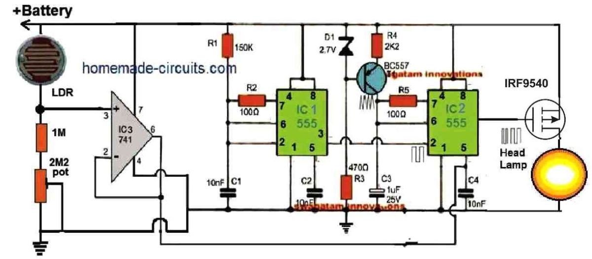
The basic idea is to increase the pulse width at the MOSFET gate and the brightness of the headlamp, when there's lower illumination on the LDR, and vice versa.

The entire circuit could be divided into 4 stages, 1) Light detector, 2) Voltage Follower, 3) Astable Oscillator, 4) PWM Controller.

The left side IC1 555 is configured as a square wave oscillator, which feeds the sample square wave to the pin#2 of the right side IC2 555 circuit which is configured as a PWM generator.

The PWM generator IC 555 transforms the square wave frequency into triangle waves and compares it with the voltage level applied at its pin#5.

The pin#5 of the right side IC2 555 stage is applied with the varying voltage due to the varying light levels on the LDR. This is implemented via the IC3 op amp buffer stage in the following manner.

The potential at the junction of the LDR and the 1M/2M2 resistors increase or decrease depending on the light level on the LDR, coming from the opposite side vehicle.

This varying potential difference is amplified and buffered by the voltage follower circuit using IC 741, whose output is then applied at in#5 of IC2 for the necessary PWM correction.

This instantaneous LDR varying levels applied on pin#5 of IC2 are compared with its triangle waves, which generates a proportionately varying PWM on pin#3 of IC2.

When the light on the LDR gets brighter, it causes the PWMs to become thinner proportionately, and when the light on the LDR gets dimmer, the PWM gets wider proportionately.

This oppositely varying PWM effect in turn causes the headlamp to get dimmer when light on the LDR is brighter, and dimmer when the light on the LDR is brighter.

Thus, depending on the light intensity on the LDR, the headlamp brightness self-adjusts, such that its brightness increases when the light on the LDR is low, and it gradually becomes dimmer as the light intensity on the LDR gets higher.

The 2M2 pot helps the user to set the maximum and the minimum headlight intensities with respect to the LDR illumination levels.

You'll also like:

  • 1.  How to Connect Car LED Downlight
  • 2.  Adjustable CDI Spark Advance/Retard Circuit
  • 3.  Car Turn Signal Flasher Circuit with Lamp Malfunction Indicator
  • 4.  Check What’s Behind the Paint of a Used Car
  • 5.  Accurate Speedometer Circuit
  • 6.  4 Solid-State Car Alternator Regulator Circuits Explored

About Swagatam

I am an electronics engineer with over 15 years of hands-on experience. I am passionate about inventing, designing electronic circuits and PCBs, and helping hobbyists bring their projects to life. That is why I founded homemade-circuits.com, a website where I share innovative circuit ideas and tutorials. Have a circuit related question? Leave a comment.... I guarantee a reply!

Previous Post: « Wheatstone Bridge Circuits Explained with Calculations
Next Post: Fuel Cells [How they Work] »

Reader Interactions

Comments

  1. Sergei Boldyrev says

    November 1, 2023 at 5:21 pm

    Thanks a lot for circuit! I would like to install this device on my motorcycle. Which LDR resistance do you recommend? thanks

    Reply
    • Swagatam says

      November 1, 2023 at 6:25 pm

      Thanks, and glad you liked the circuit.
      You can use any standard LDR available in the market. Please make sure to build the circuit step wise, and with proper understanding.

      Reply
  2. Mohammed hussain khan says

    November 11, 2021 at 8:54 am

    Thanks a lot sir very nice circuit
    Very useful thanks again

    Reply
    • Swagatam says

      November 11, 2021 at 10:10 am

      You are welcome Mohammed!

      Reply
  3. manojkumar tamilnadu says

    November 10, 2021 at 2:39 am

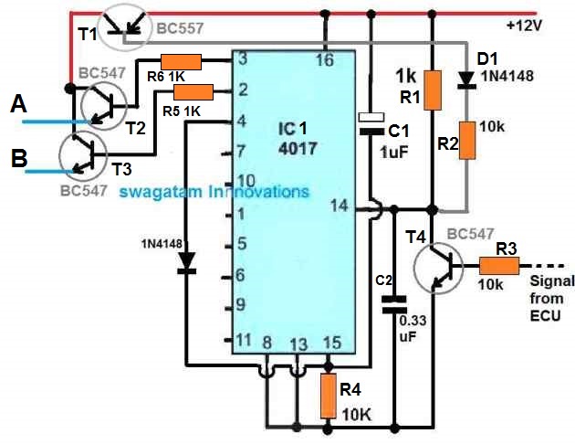
    hello swagatam.. suggest a circuit to replace common 12V BCU electronics with minimum voltage & minimum wires to operate basic functions of a motorcycle like tuning signals, indicators, multitoned warning sounds, brake light etc

    Reply
    • Swagatam says

      November 10, 2021 at 8:45 am

      Hello Manojkumar, please explain your requirement in more details, if possible I will try to figure it out….

      Reply

Need Help? Please Leave a Comment! We value your input—Kindly keep it relevant to the above topic! Cancel reply

Your email address will not be published. Required fields are marked *

Primary Sidebar

Subscribe to New Circuit Ideas

Categories

  • Arduino Projects (87)
  • Audio and Amplifier Projects (132)
  • Automation Projects (17)
  • Automobile Electronics (101)
  • Battery Charger Circuits (83)
  • Datasheets and Components (104)
  • Electronics Theory (143)
  • Free Energy (37)
  • Games and Sports Projects (11)
  • Grid and 3-Phase (19)
  • Health related Projects (25)
  • Home Electrical Circuits (12)
  • Indicator Circuits (14)
  • Inverter Circuits (87)
  • Lamps and Lights (142)
  • Meters and Testers (69)
  • Mini Projects (46)
  • Motor Controller (64)
  • Oscillator Circuits (27)
  • Pets and Pests (15)
  • Power Supply Circuits (108)
  • Remote Control Circuits (50)
  • Security and Alarm (64)
  • Sensors and Detectors (101)
  • Solar Controller Circuits (59)
  • Temperature Controllers (42)
  • Timer and Delay Relay (49)
  • Transmitter Circuits (29)
  • Voltage Control and Protection (37)
  • Water Controller (36)

Calculators

  • Battery Back up Time Calculator
  • Capacitance Reactance Calculator
  • IC 555 Astable Calculator
  • IC 555 Monostable Calculator
  • Inductance Calculator
  • LC Resonance Calculator
  • LM317, LM338, LM396 Calculator
  • Ohm’s Law Calculator
  • Phase Angle Phase Shift Calculator
  • Power Factor (PF) Calculator
  • Reactance Calculator
  • Transistor Astable Calculator
  • Transistor base Resistor Calculator
  • Voltage Divider Calculator
  • Wire Current Calculator
  • Zener Diode Calculator
  • Filter Capacitor Calculator
  • Buck Converter Calculator
  • Boost Converter Calculator
  • Solar Panel, Inverter, Battery Calculator
  • Wire Current Calculator
  • SMPS Transformer Calculator
  • IC SG3525, SG3524 Calculator
  • Inverter LC Filter Calculator

People Also Search

555 Circuits | 741 Circuits | LM324 Circuits | LM338 Circuits | 4017 Circuits | Ultrasonic Projects | SMPS Projects | Christmas Projects | MOSFETs | Radio Circuits | Laser Circuits | PIR Projects |

Recent Comments

  • Swagatam on Real MPPT Solar Charger Circuit Using Arduino, LCD, and Manual/Auto Switch
  • Obaidullah Khan on Real MPPT Solar Charger Circuit Using Arduino, LCD, and Manual/Auto Switch
  • Swagatam on 2 Compact 12V 2 Amp SMPS Circuit for LED Driver
  • Alan Bishop on AC Motor Speed Controller Circuits using Back EMF
  • Swagatam on Real MPPT Solar Charger Circuit Using Arduino, LCD, and Manual/Auto Switch

Company

  • Privacy Policy
  • Cookie Policy
  • About Me
  • Contact
  • Disclaimer
  • Copyright
  • Videos
  • Sitemap

Social Profiles

  • Twitter
  • YouTube
  • Instagram
  • Pinterest
  • My Facebook-Page
  • Quora
  • Stack Exchange
  • Linkedin
  • © 2025 · Swagatam Innovations