In this article I have explained how to build a highly efficient voltage regulator circuit using an SCR and some other external components.
This SCR voltage regulator circuit being a switching kind of regulator is more efficient than the normal 3 pin voltage regulators, or the transistor zener based series pass regulators circuits.
How the Circuit Works
The following figure exhibits the circuit of an SCR based regulated power supply. The only parts necessary for the regulation process are the SCR, R1, and the zener. When power is first switched on, the filter capacitor C1 is in the discharged condition such that its cathode is at 0 V potential.
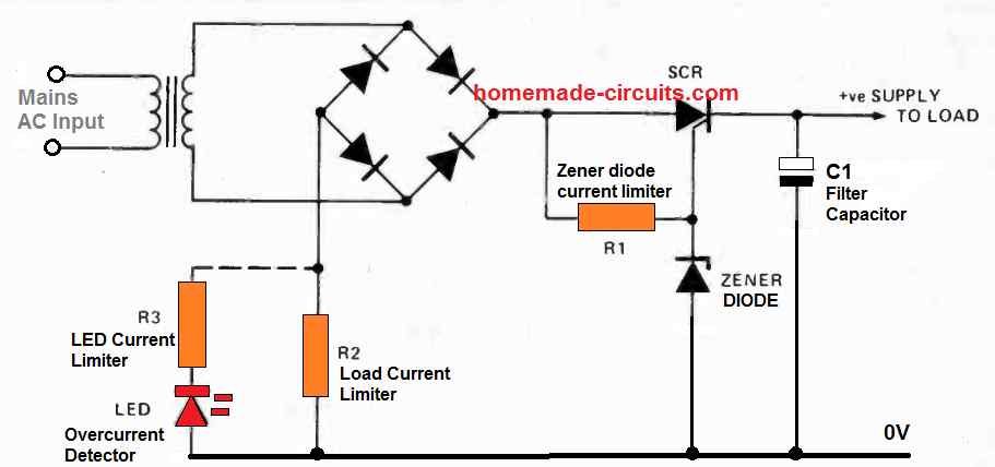
The positive half cycle waveform going out from the bridge rectifier causes the gate current for the SCR to pass through the resistor R1, which triggers ON the SCR. As soon as the SCR switched ON it starts charging the C1 filter capacitor. When the positive half - cycle ends the SCR quickly turns OFF.
As soon as the next positive half cycle arrives from the bridge, the same process repeats, charging the filter capacitor C1 until the voltage has almost reached the zener breakover voltage. As we can clearly understand, the maximum positive voltage that can arise at the gate of the SCR gate is established by the zener value.
Therefore, it means, during the above process a time comes when C1 is able to charge only up to the zener level beyond which the SCR gate is unable derive anymore positive potential, with reference to its cathode. At this specific stage the SCR is unable to sustain its firing anymore and C1 cannot charge any further.
The filter capacitor C1 discharges through the load, using the amount of power supplied from the transformer. The moment the next positive cycle arrives the SCR gate turns yet again positive, and fires, charging the C1 filter capacitor.
A couple of half cycles from the bridge are enough to lift the C1 voltage adequately to stop additional firing of the SCR. As a result the SCR triggers as essential to maintain the C1 capacitor in the "topped up" condition.
How many times the SCR has to trigger specifically depends on the current rating of the load which is being consumed from the input supply.
High Efficiency Output
You will find a couple of notably interesting characteristics of this type SCR based voltage regulator circuits.
Firstly the circuit provides a high degree of efficiency due to minimal power loss that are commonly found in either the series or the shunt type regulators.
The second great feature is that you are able to get a quick indication of the current that's being consumed by the load.
The second feature could be implemented by hooking up a LED in series with a limiter resistor R3 across the resistor R2, which acts like the load current limiter.
The LED will start blinking whenever the SCR triggers and therefore the blinking rate of the LED will directly correspond with the load current and indicate if the load has exceeded the current limit.
Parts List for 1 Amp SCR Power Supply
- Transformer = 0-12V/1 amp
- Bridge Rectifier = 1N5402 x 4 diodes
- SCR = C106 (on heatsink)
- Zener Diode = As per the required output voltage
- R1, R2 = 1 K 1/4 W
- R2 = 3 Ohm 3 watt


Comments
can this be used to feed audio amplifier ?
obviously you need to construct the negative side also
is that possible?
40 +40 bolts needed let’s say no kore than 5 Amperes
Yes, it can be used to power audio amplifiers.
For dual supply, you can just build two of these circuits and hook up the outputs in series…
i want 10000watt power what is my components make this circuit
I am moving to the Philippines where to power is 220V 60 cycle and i want to build an SCR with output
110v 10000w…..would you please send me a schismatic of such .
Thank You Kindly
I do not have this circuit with me at this moment. But instead of an SCR circuit I think it’s better to use a triac based dimmer circuit.
hii Sir,
Can we use this circuit to run a lod at 230v like a fan or a light. Also can we add a regulator to it?
No, this circuit is not for 220V load
Hi sir
Can we fix ac volt on scr 220 volt to 80 volts fix
Hi Sajid, no that’s not possible with this circuit
Hi, I am a senior citizen who is practicing electronic circuits as a hobby at home. I am a retired western Music teacher. I need small help regarding my scr btw24-600, that I want to use this one as a dimmer for 1000w bulb. If it is possible would you please send me a circuit diagram for me. I am – Lal De Saram.
If nothing is applied to the load and the input voltage is 50V, will the zener diode be damaged?
Zener cannot be damaged as long as R1 is present.
Hi, yes the SCR can be used for a 1000W bulb, but it will only control 50% AC cycles, and the bulb will be 50% dim even at maximum brightness. To get full control you must use a triac.
Hi, I missing one important value : is the mains AC Input 110Volt or 220Volt for this circuit ??
Hi, the mains can be either 120V or 220V, it’s the primary side winding of the transformer that just needs to compatible with the AC input specs
This circuit will not work properly. The condition for Zener Diode to work is that the Thevenin voltage is greater than the breakdown voltage. So it’s related to the load resistance.
Very nice