In this post I have explained a simple transistorized PWM controlled atomizer circuit for E-Cigarettes which may be used for controlling the filament heat levels of an atomizer. The idea was requested by Mr. Dave.
Technical Specifications
My name is Dave. Found your site searching for a driver circuit for a mosfet gate. I like your page but had some difficulty locating exactly what I was looking for so decided to send you an email with my request. Here,s what I'm up to.
My power source is 2 Efest 2500mAh rechargeable batteries which can be run in series or parell. They claim to be able to provide 35A output.
I would like to run them in series to provide better current to the load. I'm using a IRLB3034PBF MOSFET to provide current to a set of coils in a wick fed atomizer.
I did not see mention of such products on your site which tells me that you may not be publishing information for such a thing due to the risk of injury to those not qualified to experiment with such things. I can assure you that I am more than qualified to build a safe and reliable circuit of this type.
I'm a Master Certified Auto Technician and also own my own scope used primarily for testing electronic powertrain circuits.
I'm very familiar with PWM control circuits for automotive use. The gate control on this MIOSFET right now is a simple switch to apply current there. Can I use a 555 timer circuit to reliably control the gate or will the MOSFET overheat if I do this?
Through trial and error I can figure this out on my own, but why fry components without getting information from someone like yourself who knows what they are doing.
I have an inductive amp clamp, but have not checked to see how much current is running through the gate or the atomizer. If this information would help you determine what to use as a gate driver, I can get that for you.
At this point I'm limited on the coils I can build as they are always under full power and the current is simply controlled by the resistance level of the coils.
I'm sure you are probably more than familiar with what these circuits are like and you may have already found a solution for this.
There are plenty of recommended DC/DC voltage converters for these, but I have a box full of capacitors, resistors, and 3, 555 chips as well as 2, 55EC8LK chips. Please let me know how you feel is the best way to do this or if you could recommend a circuit with the best components to regulate the current in these.
Thanks.
Dave
The Design
An atomizer is a tiny battery operated heating device designed for heating a fed liquid until it vaporizes and escapes into the air through the given nozzle of the atomizer unit.
The liquid "juice" filled inside the atomizer could be a perfume based liquid, a repellent liquid or any similar liquid which might need vaporization for a selected purpose, depending upon the particular user.
For heating the liquid to a vaporizing level, the atomizer employs a wire coil filament, when this coil is switched with battery power across its terminals, it gets hot due to the offered resistance to the battery current, and in the process vaporizes the liquid juice filled over this coil.
Typically, atomizers come in two versions, one is the low resistance (LR) type while the other high resistance (HR) type. The low resistance version is capable of utilizing more battery current and consequently generate more heat and quick vaporization, whereas the HR or the high resistance atomizers do the same but with a lesser amount of heat and vaporization rate, due to their relatively higher coil resistance, and low current consumption.
However there's no an intermediate setting for these units which might allow the user to set a preferred vaporization rate of the liquid juice, as may be preferred by an individual using the unit.
The proposed idea of a PWM controller circuit can be effectively used to fulfill the above requirement wherein the user would be able to control the atomizer coil heat and the vaporization level at will, and as per a given specification.
The Circuit Diagram
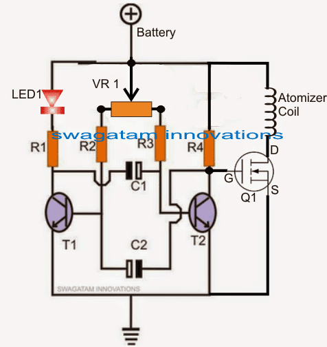
Th figure above shows a basic atomizer PWM heat controller circuit using just a couple of transistors and a single mosfet. The mosfet could be replaced with a BJT if the operating voltage is below 6V.
The circuit is a basic transistorized astable multivibrator circuit, the variable resistor VR1 decides the PWM rate for the two arms of the astable.
The LED provides an opposite indication for the PWM rates applied at the gate of the mofet. Brighter illumination indicates a narrower PWMs on the mosfet gate and therefore lower heat on the coil, conversely a dimming LED indicates a wider PWMs on the mosfet gate and consequently greater heat on the connected filament coil.
Parts List for the proposed Atomizer Circuit for E Cigarettes
R1, R2 = 1K
R2, R3 = 10K
VR1 = 100K
C1, C2 = 2.2uF/16V
T1, T2 = BC547
Mosfet = IRF540 or any mosfet capable of handling above 10V/50amp drain to source parameters.
Feedback from Mr. David Martin
Thank you for your prompt response and posting the article about it. I have the components coming from D/K, and they may be here before the weekend.
Your website has helped me learn so much about basic control circuits and I am having a blast playing around with this. I will let you know exactly how this works for my different coil designs.
I have some coil prototypes that are unique, but needed a reliable circuit to gain optimal control for these. I refuse to pay big $ for a box when I can make my own.
I have a nice box I built already, but it is just "wide open". Small switch powers up the gate and the only control is provided by the resistance level of the coil.
There are many atomizer circuit for E Cigarettes that are published and being used by DIY box mod builders, but they are over designed and somewhat wasteful with components. I really like the fact that you believe in "practical & simple".
This gives me the opportunity to gain an understanding of how these components actually work without all the confusion these more complex circuits generate for me. People are going overboard with complex driver circuits. It's a simple on/off requirement.
I have never been on the control end of electronics as I never needed to be. What happened inside the case of an automotive ECM was always a mystery to me.
As long as the inputs were correct and the control output worked, I didn't matter. If all the power and grounds as well as correct inputs were provided, I would simply replace the ECM. . Thanks again & I'll be in touch soon.
Dave

Comments
If I ordered a 10k potentiometer instead of a 100k would it be fine?
No, 10k pot will not be sufficient, it should be 100k only.
I would like to add a piece to the engineering puzzle if I may. One of the fundamental design aspects to e-vape devices is to create a lower pressure than ambient inside the vaporization chamber. Thus the reason why most all vaporizer devices have a felt air resistance when you’re drawing a hit from the mouthpiece. This is based on the principal that any liquid will boil at a lower temperature than its normal b.p. (measured at s.t.p) when a vacuum is placed on the system.
Cheers
Thank you for your interesting feedback, I hope the readers will find it useful.
Hello.
At what frequency would this PWM signal be generated at?
frequency can be determined from the values of R2/R3, C1/C2, you can use any online transistor astable software to check the frequency from these values
R1, R2 = 1k and R4 ???
R3, R4 = 10K
I want 12volt solar insects killer trap circuit
I'll try to design it and post it soon…