This mobile signal vibrator circuit will detect the wireless high frequency signals from your mobile phone and will activate the connected vibrator motor. This circuit can be used for many different customized applications.
While the implementation of an external vibrator is not electronically complicated, it encounters a simple mechanical problem with the vibrator. How can we reproduce the characteristic and highly perceptible vibrations of "real" portable vibrators?
It's quite simple, just use a motor whose output shaft is connected to an unbalanced weight, meaning an asymmetrical piece that causes significant vibrations when it rotates.
Unfortunately, if you try to make such a component yourself, it is generally heavy, bulky, and consumes too much power to be sustained for a sufficient duration by batteries.
However, fortunately ready made vibrator motors are quite easily available nowadays from the market.
Circuit Description
Creating a vibrator with this motor has been a rewarding endeavor for us.
It is important to know that when your mobile phone receives a call, it transitions from standby mode to active mode.
In response to the call, it sends several bursts of digital data at its maximum power, which is still 2W.
The power of transmission may vary depending on the reception conditions of the relay for your communication, but its initial power is sufficient to trigger the circuit, as shown in Figure 1 below.
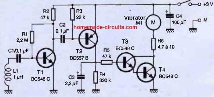
The L1 coil, which is a standard off-the-shelf component, intercepts part of the signal of the phone during its initial response to the received call, meaning when it needs to activate the vibrator.
This very weak voltage is greatly amplified by T1, and the pulses present on its collector are of sufficient amplitude to turn on T2.
T2 then rapidly charges capacitor C3, which can only discharge through R1 and the base-emitter junction of the T3/T4 pair.
These two transistors are connected in a configuration called a "Darlington pair," which is equivalent to a single transistor with a gain equal to the product of the gains of the two transistors used.
Therefore, if we use BC548C transistors here, whose minimum gain is 400, we effectively create a "super" transistor with a gain of 160,000!
This Darlington pair conducts current when the voltage across C3 exceeds approximately 1.4V, and the vibrator motor is then powered.
Since our circuit operates at 3V, we have included a current-limiting resistor R6 to prevent damaging the motor, which, as a reminder, is designed for a nominal voltage of 1.3V.
Construction
Except for the vibrator motor, all the other components are common and can be found anywhere. The printed circuit board (PCB) we propose is shown in the following figures.
It is small enough to fit in a case that won't take up much space in your pocket alongside your mobile phone.
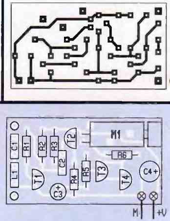
The component placement is straightforward and is indicated in the figure above. Start with the passive components and finish with the semiconductors and the motor.
Pay attention to the polarity of the components and make sure to connect the motor with its red wire to the positive power supply. The power supply should be at 3V.
As for the case in which you will place your circuit, you can use two R3 1.5V batteries, silver oxide button cells also rated at 1.5V, or a single lithium battery (such as CR2032) with a nominal voltage of 3V.
An on/off switch should be included because even though the circuit's idle power consumption is very low, reaching only 900uA, it will still unnecessarily drain the batteries.
The circuit operates immediately if no wiring errors have been made. Simply place it a few centimeters away from your mobile phone and make a call to observe the vibrator activating within a second of receiving the call.
The vibrator stops as soon as the phone stops ringing. The duration of the vibrator's activation also depends on the exact value of capacitor C3.
If you find the duration too long, you can reduce it by slightly decreasing the value of resistor R4.
You can also adjust the value of resistor R6, which can be between 4.7 and 10 ohms, according to your preference.
A lower value will make the motor spin faster, resulting in more pronounced vibrations.
In our experience, a value of 10 ohms provided satisfactory results while ensuring a long lifespan for the motor, as it is not excessively stressed.


Comments
Hi
If you were to simulate this circut in ORCAD etc. How would you simulate the Antenna part ( L and C1)
Could you just replace it with a Sinus wave former tuned to the resonace frequency. Im trying to figure out what the minimal signal strenght is for the whole circut for it to work
Hi, sorry, I am not good with simulator softwares so have no idea how to solve the issue.
Hi again Thx for prevoius answer
Btw
How did you end up with the values of C1 and L. Arent mobile phones using a much higher frequency?
In the above design, the L1 is detecting the leaking RF power of the mobile network, so the frequency is not relevant here.
And there is no LC tank circuit or resonance necessary for this circuit.
C1 acts like a blocking capacitor, not a resonance capacitor.