In this post I have explained how to make a simple digital clock using Arduino and a 16 x 2 LCD display.
Introduction
As an electronics enthusiast at a stage we would have thought, how to make a digital clock, especially who are interested in the field of digital electronics. In this article we are going to see how to make a digital clock and the design is so simple that a noob in Arduino can accomplish the project without any head ache.
This digital clock has just two main components, the Arduino and LCD display. The Arduino is the brain of the clock, which does mathematical and logical functions to updates the clock every second.
Prototype Image:
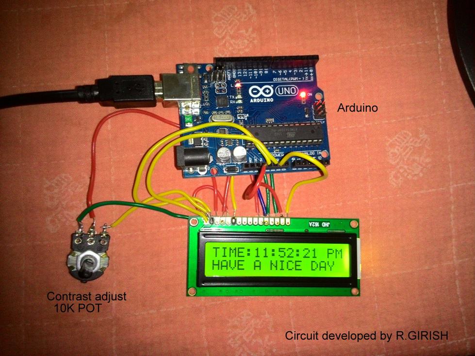
The LCD screen is a standard 16 pin interfaced display. It has 16 rows and 2 columns, this means it can display 16 ASCII character in a row and it has two columns and that’s why it is called 16x2 display.
The wire connection between the LCD and Arduino is standard and we can find the similar kind of connections in most of the other Arduino-LCD based projects.
The potentiometer is used to adjust the contrast of the display.
The user must set this optimally so that the user can see the displayed digits/characters properly under all light situations.
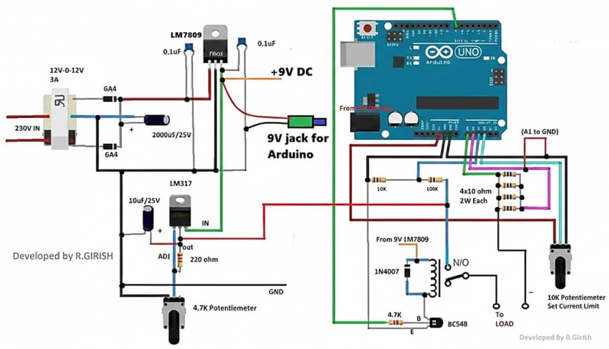
There is backlight which enables the user to see the display during dark situation. The arduino can be powered externally from DC jack from 7 volt to 12 volt.
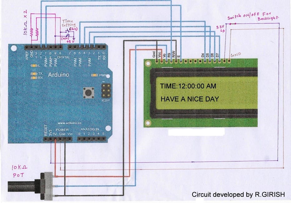
Circuit diagram:
ARDUINO PROGRAM CODE:
//-------- Program developed by R.GIRISH-------//#include <LiquidCrystal.h>
LiquidCrystal lcd(12,11,5,4,3,2);
int h=12;
int m;
int s;
int flag;
int TIME;
const int hs=8;
const int ms=9;
int state1;
int state2;
void setup()
{
lcd.begin(16,2);
}
void loop()
{
lcd.setCursor(0,0);
s=s+1;
lcd.print("TIME:" );
lcd.print(h);
lcd.print(":");
lcd.print(m);
lcd.print(":");
lcd.print(s);
if(flag<12) lcd.print(" AM");
if(flag==12) lcd.print(" PM");
if(flag>12) lcd.print(" PM");
if(flag==24) flag=0;
delay(1000);
lcd.clear();
if(s==60) {
s=0;
m=m+1;
}
if(m==60)
{
m=0;
h=h+1;
flag=flag+1;
}
if(h==13)
{
h=1;
}
lcd.setCursor(0,1);
lcd.print("HAVE A NICE DAY");
//-----------Time setting----------//
state1=digitalRead(hs);
if(state1==1)
{
h=h+1;
flag=flag+1;
if(flag<12) lcd.print(" AM");
if(flag==12) lcd.print(" PM");
if(flag>12) lcd.print(" PM");
if(flag==24) flag=0;
if(h==13) h=1;
}
state2=digitalRead(ms);
if(state2==1) {
s=0;
m=m+1;
}
}
//-------- Program developed by R.GIRISH-------//
NOTE: The above program is verified and error free. In case you got any warning or error, please add the LiquidCrystal library manually.
Time setting:
There are two push button one for setting hours and another for setting for minutes. Pressing either one will increment the corresponding digits. For setting hours press hrs the button till the correct time displays, similarly for minutes.
NOTE:
· While setting time the keep the button depressed till the desired time reaches. Pressing the button momentarily may not change the time.
· Each digit gets incremented only second after second, this is because the whole loop of the program delayed for 1 second.
· The seconds’ digit goes from 01 to 60 and loops again and won’t display “00” as traditional digital clock does.

Questions & Answers
I want to add alarm features to this project .What will be the complete program code for that ?
designing customized codes will require a fee to be paid for the service
Sir can you send sketch for multi function ledchaser 12 channel
dude the time lags for about 10mins a day, so for a week its about an hour slow…
Thanks for the reply GR, due to the time lag problem, i purchased an RTC DS1307 IC, i still dint try with it. Hope it works well…
Hi kaushik,
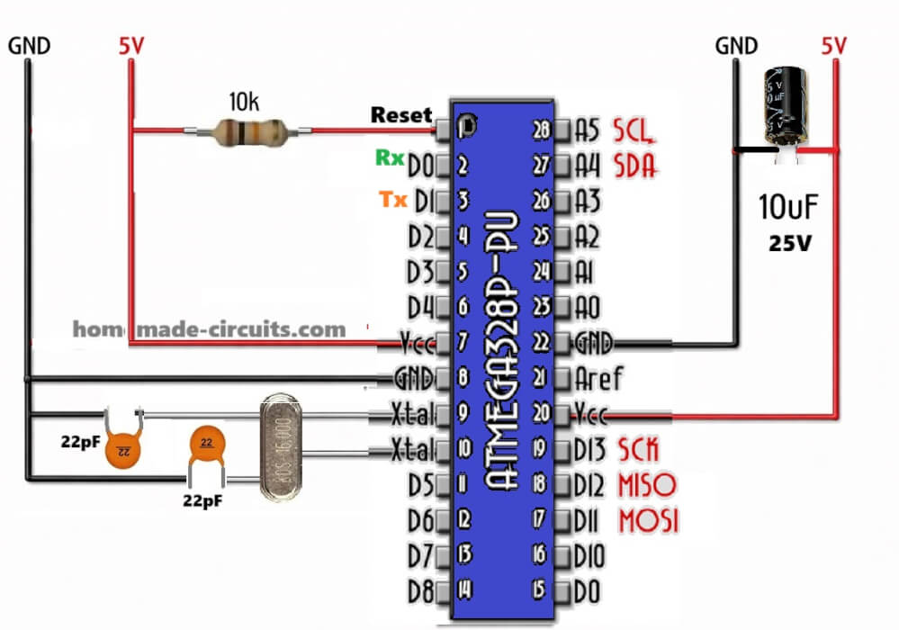
The time lag is due to the ceramic based resonator in the ATmega328P, the delay function is independent of the crystal. It varies with ambient temperature, but we can compensate it by adding few millisecond to delay function, for example try delay(1050); instead of delay(1000); calculate the time lag and add few milliseconds.
If your clock leads the time try reducing delay.
Regards