In this post I have explained a simple radio repeater circuit which can be built by any new hobbyist or a radio amateur for communicating over long distances using ordinary transmitters and radio receivers.
In this article we are going to see what radio repeater is, how it works and how to build one in a hobby lab. In the end you would be able to build a micro repeater station for the proposed full duplex communicator design in this article. This may be used for short distance communication when you are on a camp or use as an intercom or some similar applications.
NOTE: Follow the strict rules and regulation implemented by your local and country government before proceeding with this project.
What is a Radio Repeater
Here we are taking walky-talky as an example. A walky-talky is a half-duplex communication device, which means the communication takes place in one direction at an instant. For example: Person ‘A’ can talks through walky-talky to person ‘B’, but person ’B’ can’t reply simultaneously and vice versa.
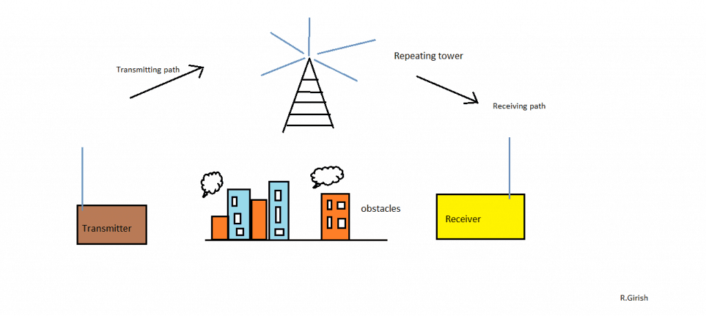
During propagation of modulated signal from walky-talky ‘A’ to walky-talky ‘B’, there could be obstacles between them, such as mountain, buildings, trees, etc. These obstacles could potentially reduce the range of the propagated signals, thus the person at the receiving end may hear broken signals.
To avoid this kind of issues we go for a radio repeater. A radio repeater repeats the transmitted signal to wider range, even over several 100 KM, which ensures that the receiving party will receive a clear signal.
In other words a repeater extends the range of the signal being transmitted.
The repeater station is place on top of hills, so that it can receive maximum signal from a node and re-transmit to single or multiple nodes with less distorted signal. The repeater must be within the range of the transmitting node, only then the repeater may be able to re-broadcast the signal to multiple nodes.
The full duplex communicator design:
A full duplex communication is a two way communication, in which both the parties are able to communicate simultaneously. To keep the design as simple as possible we use a standard FM radio as the receiver and a simple FM transmitter.
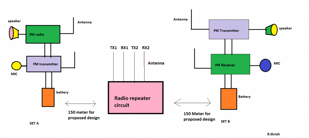
We need two FM radios and two transmitters to establish full duplex communication. In between two communication sets the repeater will be placed to extend the signal.
A good example for full duplex communication is telecommunication and the proposed design works similarly. The SET ‘A’s FM receiver is tuned to SET ‘B’s transmitter and SET ‘B’s FM receiver is tuned to SET ‘A’s transmitter. Thus we can achieve simultaneous communication between them.
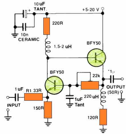
The given transmitter design can transmit up to 200 meter on best case scenario. Adjust the trim capacitor for tuning the transmitter.
FM Transmitter Schematic for the proposed radio repeater circuit:
![]()
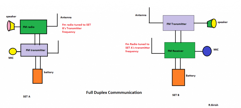
Full duplex communication: (without repeater)
The Repeater Design:
The given radio repeater circuit is a two channel design. A channel consists of one transmitting and one receiving frequency; here we have two such sets.
The radio repeaters in real world consist of several numbers of channels. Here we need two FM transmitters and two receivers (FM radio) for 2 channel design. We can use same transmitter circuit as shown above.
When the repeater comes in between the transmission and reception, the whole system gets slightly complicated. Let’s assume some factors and simulate the situation:
· Let, SET ‘A’s transmission frequency be 90MHz. Then the receiving frequency at repeater must be 90MHz (RX1). Let the repeating frequency at TX1 be 92MHz. Then the receiving frequency at SET ‘B’ must be 92MHz. similarly for another channel.
· All the frequencies used in repeater must not be used more than once. For example: 90MHz at TX1 and this frequency should not be used anywhere in the repeater circuit.
· The transmission frequency, repeating frequency and receiving frequency must be well determined before communication just to avoid confusion.
NOTE: Here the node represents one set of transmitter and receiver. Distance between node and repeater is 150 meter is an assumption; it could be greater or less depending on environment and antenna length. Use a radio with good sensitivity for this project.
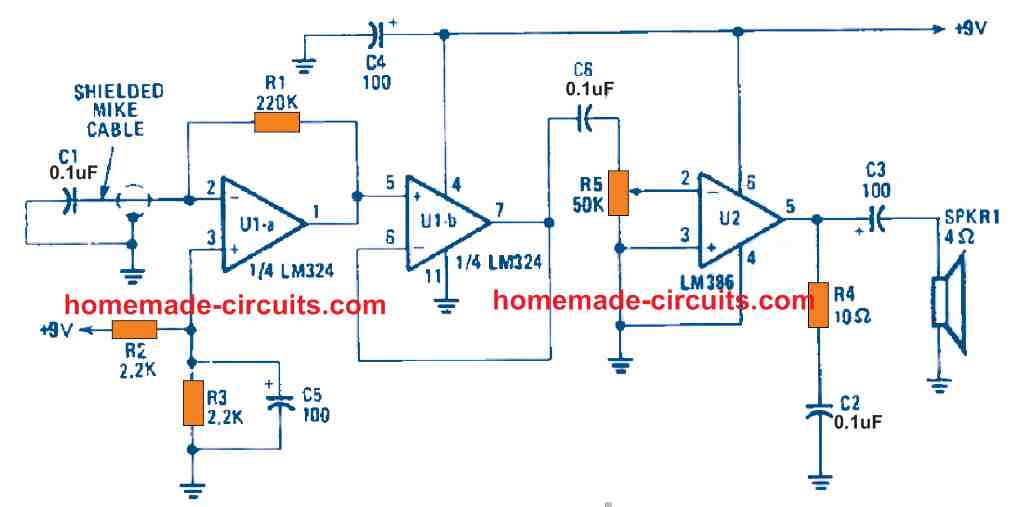
Repeater diagram:
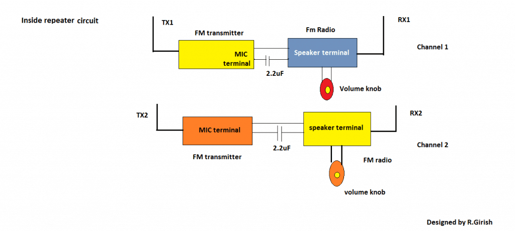
NOTE: Adjust the volume knob optimally so that the right amount of volume goes to the transmitter. Don’t ramp-up the volume to maximum, otherwise there could be a good chance of distortion in re-transmission.

Comments
We are looking for a simple schematic RPT control using 2 of 555 and Q-4 or so.
Want Hang timer and Time out timer as well fed by Cos.
We have some WR circuits with more than what we need.
Or 1 556.
If possible I will try to design it, and let you know soon:
How to make cross band duplex repeater controller
Sorry, I am not sure about it…
Requirement for CNR-900M and Motorola CP1180 Retransmission Setup
I want to set up a CNR-900M military radio and a Motorola CP1180 commercial radio in retransmission mode so that they automatically relay audio between each other. The goal is to establish a system where:
1. When one radio receives a signal, the other radio should automatically transmit it.
2. This should work in both directions, meaning:
• If the CNR-900M receives a transmission, it should trigger the CP1180 to transmit the same message.
• If the CP1180 receives a transmission, it should trigger the CNR-900M to transmit the same message.
3. The process should be fully automatic without requiring manual PTT (Push-To-Talk) operation.
Sorry, I have no idea how to configure the CNR-900M and Motorola CP1180 Retransmission Setup
How many mm is l1?
.Lamentablemente no expuso el circuito del sistema de conmutacion para ambas radios.
O sea en si mismo el circuito repetidor……….
Why should i need a mic in repeater Circuit?
And..Can you plz draw! how current is pass through the whole circuit
sir,…I can not understand the repeater circuit…. and can I used another transmitter???
yes you have to install a new transmitter at every selected node for enhancing the range